What is a Shaft Centerline Diagram?
Alan Friedman, Cat IV, CRL, CMRP, Author; Founder/CEO of Zenco Vibration Experts
Posted 3/14/2024
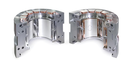
A shaft centerline diagram is a plot used in the vibration analysis of journal bearings. It is also called a shaft average centerline diagram. The purpose of this graph is to display the average position of the rotor in the bearing. In short, for different bearing types, there is an expected or “normal” position of the shaft in the bearing. If this position changes, it can indicate a problem.

Figure 1 above shows two mass-spring systems vibrating at the same amplitude and frequency. They are, however, vibrating around different points, (the horizontal dashed black lines.) You can think of the shaft centerline diagram as the point the shaft is vibrating around.
If the blue wave in the figure above was electricity, it would be an alternating current (AC). This is what the AC output of a vibration sensor would look like if it was measuring the vibration of the mass in the figure. If you look at the black dashed horizontal lines, this looks like direct current (DC) voltage. The proximity probes used to measure the shaft centerline diagram put out both an AC and DC component. Because we are interested in position rather than vibration in this plot, we only keep the DC component. This is called DC coupling.
Proximity Probes
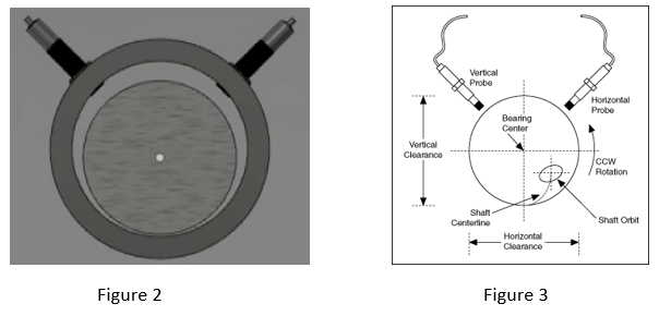
One typically uses two proximity probes, also called eddy current probes, when monitoring a journal bearing. The probes are permanently installed and mounted 90 degrees from each other (Figure 2). This gives us a two-dimensional view of the shaft’s position in the bearing. The AC voltage from these probes is used to measure shaft vibration and is often displayed in a 2D plot called an orbit. Figure 3 shows the relationship between the shaft centerline and the orbit. You can think of the centerline as the point the shaft is orbiting about.
As a shaft is run up in speed, the rotating shaft forces the oil to form a wedge in the bearing (Figure 4). The rotor will then sit on this oil wedge as it rotates around. Figure 5 is the shaft centerline diagram. The blue numbers on the plot are shaft RPM. The red line shows how the center point of the shaft has moved as the machine is sped up to running speed. In this case, up and a little to the right, which is normal for a tilt pad bearing rotating counterclockwise. Figure 6 shows an abnormal centerline plot where the rotor is too far to the right edge of the bearing. This could be the result of misalignment.

The shaft centerline plot is essential for journal bearing monitoring. Abnormal rotor positions can indicate all sorts of problems. This plot should be routinely measured and analyzed when monitoring journal bearings.

This is just a brief introduction to centerline diagrams. If you would like to learn more, why not come to one of my courses? Cat I, II and III are available with certification in accordance with ISO 18436-2. Cat I and II are available in Spanish.
Sign up for upcoming training today.
Read about the benefits of becoming a Certified Vibration Analyst.

Alan Friedman
Alan, aka the Vibe Guru, has over 30 years of vibration analysis experience, He has trained 1000’s of students around the world up to Category IV. One of the things that makes Alan a great teacher is his ability to teach people where they are at. Whether you are a math challenged millwright, an engineer or a PhD, Alan will challenge you without overwhelming you. If you are interested in condition monitoring you can also check out his book: Audit It. Improve It! Getting the Most from your Vibration Monitoring Program or hire him for an on-site program audit.
Related Articles
What is Vibration?

Web Based Vibration Analysis Programs

Vibration & Ultrasound Technologies: A Possible Integrated Inspection Tool?

Vibration Pen, Shock Pulse Measurement (SPM), & Vibration Analysis - What's the Difference?

Vibration Analysis Reveals Poor Motor Mounting Structure

Integrating Vibration and Wear Debris Analysis for Machine Condition Monitoring

Inspecting Seals with IR Thermography

In-Process Motor Testing Results Using Model Based Fault Detection Approach
Infrared Thermography and Distribution System Maintenance
How Unbalance Affects Bearing Life

Data Analysis Tip 2 – Create a Vibration Test and Analysis Guide

Certification of Vibration Analysts in a Dynamic Job Market
DC Motor Brush Holder and the Performance of Carbon Brushes

DC Motor Carbon Brushes for Elevators: Composition, Function, Solutions

Understanding Shaft Alignment: Basics

What is Vibration? Linear and Non-Linear Systems

10 Reasons Why You Should Audit Your Vibration Monitoring Program NOW!

10 Components of a Successful Vibration Program - Part 1

10 Components of a Successful Vibration Program - Part 2

10 Components of a Successful Vibration Program: Part 3

Vibration Analysis Using ADCs Keeps Industrial Equipment Working


