DC Motor Brush Holder and the Performance of Carbon Brushes
Jeff D. Koenitzer
Introduction – What is a Motor Brush?
A DC Motor carbon brush is an electrical contact which makes a connection with a moving surface. Optimal performance on motors, generators and other types of moving contact applications will be attained only when the carbon brush, the brushholder and the contact surface are properly designed and maintained. All three components are critical factors in a complex electro-mechanical system.
The DC Motor brush holder, as the name suggests, holds the brush so that the brush can perform properly. Holders provide stable support in the proper position in relation to the contact surface and often provide the means for application of the contact force on the brush.
For many decades brushholders had received little attention. New rotating equipment was supplied with copies of the same old brushholder designs. Typically, when performance problems occurred the focus had been on the brush as this was the part exhibiting rapid wear. In the early 1980’s Helwig Carbon led the industry towards the consideration of brushholders and particularly spring pressure as a common cause of many brush problems. Further, recent motor brush holder developments and the coordination of the designs of constant pressure holders with Red Top brushes have resulted in significant advancements in performance and life.
The purpose of this paper is to review the critical areas of consideration for brushholders in relation to the proper functioning of brushes. The most important factors are 1) maximum stability of the carbon in the holder, 2) proper positioning of the brush on the contact surface, and 3) minimum resistance through the brush and holder portion of the electrical circuit.
Motor Brush Holder Size Dimensions
The fit of the carbon portion of the brush in the holder is critical for stable electrical contact. If there is inadequate space between the holder walls and the thickness and width of the brush, there is potential for binding of the brush in the holder particularly with increased temperature and contamination. On the other hand, an excess amount of space between the holder and the carbon will result in an unstable electrical contact as the brush face can move tangentially or axially within the holder.
The motor brush holder and brush tolerances on the thickness and width therefore must be well coordinated. Brushes are machined undersize per NEMA tolerances or per drawing specifications while brushholders are made oversize. As a general guideline for brushholders, industrial sizes typically should be held oversize to a tolerance of +.002/+.008″. Smaller frame units with a brush thickness less than .500″ and greater than .125″ should have holders with a tolerance of +.001/+.005″. Micro size units with brushes of thickness .125″ or less should have holders held to a tolerance of +.001/+.003″.
Over a long period of usage the thickness dimension on a holder can become worn from brush movement or distorted from heat. Therefore, it is important to periodically measure the thickness and width dimensions on the top and bottom of the holders to ensure they are within tolerance and that the brush will have adequate support for a stable electrical contact.
When motor and generator brushholders are subjected to high temperatures, it may be necessary to provide extra compensation for thermal expansion depending on the temperature rise and the degree of heat dissipation. In these cases it is easier to reduce the brush thickness and width dimensions slightly to avoid sticking in the motor brush holder rather than adjusting holder dimensions. Metal graphite brushes with over 50% metal content by weight are manufactured with an increased undersize tolerance per NEMA standards as they usually carry higher current, generate more heat, and have a higher coefficient of thermal expansion than non-metal grades.
Brush and holder length can also have a significant effect on the stability and performance of the brush. Most often the length is limited due to the space available within the frame. There are, however, also practical length limitations due to the excess resistance of a long piece of carbon. As the carbon length is increased the resistance of the current path from the shunt to the contact surface is increased. At the same time the amount of contact area between the carbon and the longer holder is increased and the corresponding contact resistance is decreased. This then creates the potential for distorted current flow directly between the holder and the carbon rather than through the shunting.
On the other hand, short brush and holder designs are more susceptible to instability at the contact surface. There is potential for a higher degree of brush tilt in the holder since the length of support is less in relation to the brush thickness.
In addition to dimensional concerns the insides of the motor brush holder must be smooth and free of all obstructions including burrs. If a used brush has any straight scratches down the sides of the carbon then there are protrusions inside the brush box, which will restrict the brush from making proper electrical contact. Rough handling of brushholders can cause distortion of the metal and effect the critical inside dimensions of the brush cavity. Holders made from metal stampings are particularly susceptible to irregularities on the inside dimensions and on squareness. Broaching is generally accepted as the best manufacturing method for assurance of consistent inside dimensions and a smooth finish.
Holder Position
The holder position will determine the location of the brush on the moving contact surface. For slip ring applications the holders are usually located around the top portion of the ring for ease of access. In this position the weight of the brush contributes to the contact force. If holders are mounted on the underside of a contact surface then additional spring force may be necessary to compensate for the weight of the brush.
On DC machines with commutators proper positioning of the holders in relation to the field poles is critical. The brushes should be equally spaced around the commutator. This spacing can be checked by wrapping a paper tape around the commutator, marking the location of the same edge of each brush, and then measuring the distance between marks on the paper.
The brushes must also contact the commutator within the neutral zone where voltage levels are near zero. When the holder position allows the brush to make contact outside the neutral zone there will be higher bar to bar voltages under the brush, circulating currents, bar edge burning, and damage from arcing.
Holder Angle
The most common angle for motor brush holder mounting is 0 degrees, i.e. perpendicular to the contact surface. Most slip rings and reversing commutator applications make use of this so-called radial mount. The advantages are ease of holder installation, maximum spring force transferred to the contact surface, and fair stability of brush contact upon reversal of direction.
Any brush face movement within the holder will result in a change in the contact surface. The most stable surface contact will occur when the top and bottom of the brush are always held to the same side of the holder regardless of the direction of rotation. Angle holder mountings were developed to increase this stability and the effective area of the brush contact. However stability will occur only when the correct angles are used in relation to the direction of rotation.
When the entering edge is the short side of the brush or a trailing position the face angle should be 20 degrees or less. At greater angles the action of the rotation and the spring force wedges the brush into the bottom corner of the holder and causes high friction and an unstable contact. Normally trailing brushes also have a shallow top bevel.
When the entering edge is the long side of the brush or a leading position the face angle should be 25 degrees or more. At angles of 20 degrees and less the action of the rotation pulls the bottom of the brush to the opposite side of the holder from the top of the brush. Leading brushes should have a top bevel of 20 to 30 degrees.
A stable contact can be maintained in either or both directions of rotation with brush face angles between 20 and 25 degrees. The potential disadvantage of holder angles is the loss of effective downward force of the spring. A portion of the spring force is dissipated in holding the brush stable to one side for the holder. The loss in downward contact force for various angles are as follows:
Angle Degrees Loss in Downward Force
5 0.4%
0.4%
10 1.5%
15 3.4%
20 6.0%
25 9.4%
30 13.4%
35 18.1%
40 23.4%
45 29.3%
The spring force should be increased to compensate for the loss of effective downward force from the action of the brush angle in holding the brush to the side of the holder. If a brush has bevels of 20 degrees on the top and 30 degrees on the bottom then the spring force should be increased 6.0% + 13.4% or about 20% to maintain the proper level of effective downward contact force at the brush face.
In the special case of post mounted double holders commonly used on slip rings, the best design would allow both brushes to make contact at zero degrees or perpendicular to the ring. Any angle will result in one brush in the pair operating with less contact stability.
Return to top of page.
Motor Brush Holder Mounting Height
The vertical position of the holders above the contact surface is very important in assuring proper brush support throughout the wearable length of the rush and for proper positioning on the contact surface.
When a brushholder is mounted too high above the contact surface or when the surface has been turned down to a significantly smaller diameter, there will not be adequate support for the carbon as the brush wears to a short length. This will contribute to increased electrical wear due to the instability of the contact.
The holder mounting height should be proportional to the size of the unit. On the large frame sizes the holders should be mounted a maximum of .125″ above the contact surface. In a few cases units operated with intentional runout of the contact surface which must be taken into consideration. The small micro frame sizes should have a holder mounting height of approximately .032″. During holder mounting a flexible mounting pad of the appropriate thickness can be placed on the contact surface to ensure consistent height and spacing. This pad also helps protect the commutator from damage during mounting.
There are several common problems related to excess height of the holder. When a commutator has been turned down several times angled brushes will make contact in a different position. With steep bottom bevels and significant decreases in diameter the location of the brush contact could even move outside the neutral zone. There will be a significant increase in wear unless the holder is moved closer to the commutator or the neutral is adjusted.
Although single post mounted holders can be rotated to move the holder closer to the commutator, the position of brush contact will change. As above it is very likely that adjustment of the neutral position will be required to avoid edge arcing.
On V-shaped toe-to-toe holders which are mounted too high above the commutator the brushes can interfere at the toes. This will result in one or both brushes not making contact with the commutator. It is especially important that these old style holders are mounted sufficiently close to the commutator to avoid this problem.
Spring Force
Many inventive methods have been used for the application of the contact force on brushes. These included clock type springs, torsion bars, lever springs, helical coil springs, and constant force negator springs. As noted in the graph shown below the brush wear rate will change as the spring pressure changes. This is one of the most important concepts in understanding brush performance.
There has always been a problem with an accelerating rate of wear as the brush gets shorter due to the declining spring force and the dramatic increase in electrical wear. The most consistent brush performance will be attained when the spring force is virtually constant at the correct level throughout the wear length of the brush.
The use of the proper constant force springs can be a significant advantage with consistent minimal wear rate of the brushes, reduced wear of the contact surface, less carbon dust, and much lower overall maintenance costs on the unit.
Testing and application experience have resulted in the following recommended ranges of spring pressure:
Spring Pressure Recommendation
Application Spring Pressure
General Industrial
4.0-6.0 PSI
Fractional HP Motors 4.0-7.0 PSI
Traction 5.0-8.0 PSI
Induction & Sync Motors 3.5-4.5 PSI
High Speed Slip Rings 2.25-2.75 PSI
Elevator Generators 3.5-4.0 PSI
35 18.1%
40 23.4%
45 29.3%
When operating conditions vary from the standard then some adjustment in spring force can improve performance. If the current density is very low, the humidity is very low, or the speed is extremely high then a slightly lower spring force than above can be an advantage. However if the current loads are high, the speed low, there is contamination causing over filming, or where external vibration and roughness of the contact surface are affecting the brush, then a spring force near the high end of each range is recommended.
The unique set of conditions on each application will result in its own specific graph and numbers for the ideal spring force to obtain minimum wear of the brushes and the contact surface. Often times a change in spring force will have a far more dramatic effect than a change in brush grade. Several original equipment manufacturers test for the ideal spring force prior to testing different brush materials.
The springs on all holders should be checked every 2 or 3 brush changes to ensure the pressure is still within the recommended tolerance and the that the force is consistent on all holders. The force of the spring must first be measured with an accurate scale. This value is then used to calculate spring pressure as shown below.
If the spring pressure value is below the recommended range then the springs should be replaced to avoid accelerated wear of the brush and the contact surface.
Electrical Connections
The primary function of the brush involves conducting current. In many cases the brush holder is also a part of this electrical circuit. Therefore it is necessary that all electrical connections are of minimal resistance to provide the best path for current flow from the main lead connection to the contact surface. Corrosion, contamination, or electrolytic action over a period of time can cause dramatic increases in resistance which then requires cleaning. Careless installation of the brushes or the holders can lead to loose connections. Any high resistance in the brush circuit will result in excess heat or an undesirable path of current flow and unequal loading of the brushes.
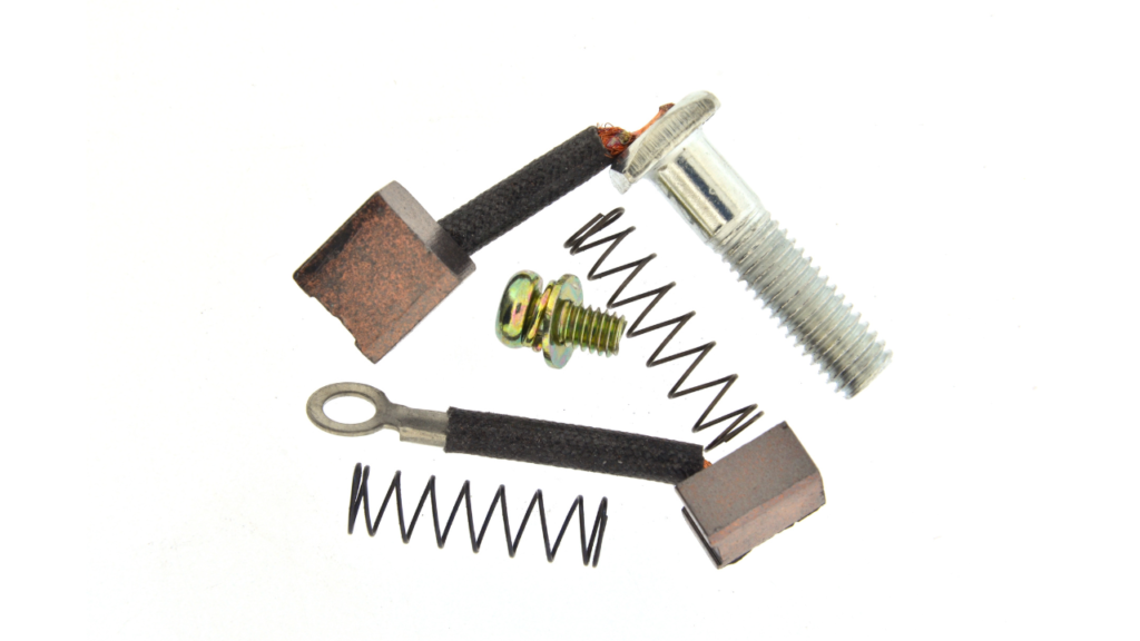
On fractional horsepower cartridge style brushholders with captive coil spring type brushes the current should flow from the clip connector at the bottom of the holder up the brass insert to the cap on the end of the brush and then down through the shunt to the carbon. The brushes fail very quickly if the round or eared cap on the end of the brush does not make proper contact with the brass holder insert. When this condition exists current will flow directly from the brass insert to the spring or to the carbon. In either case there will be extreme heat, loss of brush contact, commutator wear, and eventually motor failure.
Another problem with larger frame sizes can occur when the holder mounting is part of the electric circuit. If the holder mounting surface becomes dirty, corroded, or even painted over then current will again need to follow another path and thereby cause problems.
Summary
The general knowledge and experience in the field on rotating equipment has been slowly declining for many years. In addition brushholders have seldom ever received proper attention during trouble shooting or as part of a maintenance program. Therefore it is hoped that the above information will be helpful in creating awareness of the potential problems with brushholders as a very critical component in the satisfactory performance of carbon brushes on motors, generators, and other types of sliding contacts. The important factors to check for proper functioning of the holder and brush are:
1. Inside holder dimensions
2. Holder spacing
3. Holder angle
4. Holder height
5. Spring force
6. Electrical connections
When there is an opportunity to implement new holders, the use of the principles mentioned above along with the coordination of the latest constant pressure holder and Red Top.
Click here to read more about Carbon Brushes for DC Motors or download the full pdf.
Need something more specific? Check out DC Motor Carbon Brushes for Elevators: Composition, Function, Solutions: by Jeff D. Koenitzer
Related Articles

What is Predictive Run to Failure?


Preventive vs. Reactive Maintenance: Don’t Neglect Makeup Water and Condensate Return Treatment – Part 2

Preventive Maintenance for Wintertime Heating

Unmanned Aircraft Systems and the Future of Autonomous Inspection