[webinar] Embracing Digital Transformation in Maintenance & Plant Operations | March 13 at 10AM EST – Register Now
A Guide to Matching Electric Motors with Hydraulic Power Units
A Guide to Matching Electric Motors with Hydraulic Power Units
Ronald R. Gould, CFPE
Sizing electric motors correctly for hydraulic power units can save a sizable amount of money over the life of the equipment. If system pressure and flow are constant, motor sizing simply boils down to the standard equation:
hp = QP / 1714EM
where: hp is horsepower Q is flow in gpm P is pressure in psi, and EM is pump’s mechanical efficiency.
However, if the application requires different pressures during different parts of the operating cycle, you often can calculate root mean square (rms) horsepower and select a smaller, less-expensive motor. Along with the calculation of rms horsepower, the maximum torque required at the highest pressure level of the application also must be found. Actually the two calculations are quite simple.
For example, such an application might use a 6-gpm, 3450-rpm gear pump to power a cylinder linkage that operates for an 85-sec cycle. The system requires 3000 psi for the first 10 sec, 2200 psi for the next 30 sec, 1500 psi for the next 10 sec, and 2400 psi for the next 10 seconds. The pump then coasts at 500 psi for 20 sec, followed by 15 sec with the motor off.
It’s tempting to use the standard formula, plug in the highest-pressure segment of the cycle, and then calculate:
hp = (6)(3000) / (1714)(0.9) = 11.7 hp for 10 sec.
To provide this horsepower, some designers would choose a 10-hp motor; others would be ultra-conservative and use a 15-hp motor; a few might take a chance with 7.5 hp. These motors in open drip-proof C-face models with feet would list at about $570, $800, and $400 respectively, so there could be savings of $170 to $400 per power unit by choosing the 7.5-hp motor – if it will do the job.
To determine this, first calculate the horsepower for each pressure segment of the cycle:
hp1 = 6(2200) / (1714)(0.9) = 8.5 hp for 30 sec. hp2 = 6(1500) / (1714)(0.9) = 5.8 hp for 10 sec. hp3 = 6(500) / (1714)(0.9) = 1.9 hp for 30 sec.
The rms horsepower is calculated by taking the square root of the sum of these horsepowers squared, multiplied by the time interval at that horsepower, and divided by the sum of the times plus the term (toff /F), as indicated in the box at the bottom of this page.
Substituting the example values into the boxed equation and solving reveals that hprms equals 7.2. Thus, a 7.5-hp motor can be used from the standpoint of horsepower alone. However the second item, maximum torque, still must be checked before reaching a final decision. The maximum torque required to drive this particular pump will be found at the highest pressure – because the gear pump’s output flow is constant. Use this equation:
T = DP / (12)(6.28)EM
where: T is torque in ft-lb, and D is displacement in in.3
For this example, D = (6)(231) / (3450) = 0.402 in.3 Then T = (0.402)(3000) / (12)(6.28)(0.9) = 17.8 ft-lb.
Because electric motors running at 3450 rpm generate 1.5 ft-lb per hp, the 17.8 ft-lb of torque requires (17.8 / 1.5) or 11.9 hp at 3000 psi. This checks out closely enough for the example application. (At other standard motor speeds: 1725 rpm generates 3 ft-lb per hp; 1150 rpm, 4.5 ft-lb per hp; 850, 6 ft-lb per hp.)
Now the second criteria can be checked against what the suggested motor can deliver in torque. What is the pull-up torque of the 7.5-hp motor selected? Because the torque is least as the motor accelerates from 0 to 3450 rpm, it must be above 11.9 ft-lb with an acceptable safety margin. Note that a motor running 10% low on voltage will produce only 81% of rated pull-up torque: i.e., (208/230)2 = 0.81. Reviewing motor manufacturers’ performance curves will show several available 7.5-hp models with higher pull-up torque. Any of these motors could be a good choice for this application.
Both motor criteria now have been verified to match the motor with the appropriate hydraulic power unit. The rms horsepower is equal to or less than the rated motor’s horsepower. The motor’s pull-up torque is greater than the maximum required.
There are occasions when you might want to permanently change the amount of fluid you are pumping, or change the discharge head of a centrifugal pump. There are four ways you could do this, of the four methods the middle two are the only sensible ones. In the following paragraphs we will learn what happens when we change either the pump speed or impeller diameter and as you would guess other characteristics of the pump are going to change along with speed or diameter.
There are occasions when you might want to permanently change the amount of fluid you are pumping, or change the discharge head of a centrifugal pump. There are four ways you could do this, of the four methods the middle two are the only sensible ones. In the following paragraphs we will learn what happens when we change either the pump speed or impeller diameter and as you would guess other characteristics of the pump are going to change along with speed or diameter.
At the high temperatures and pressures in boilers, well-operated and maintained chemical feed systems are critical for preventing corrosion. However, the task becomes more challenging if corrosion products from other areas of the system travel to and deposit on boiler tubes. The chemistry beneath deposits can be quite different than in the bulk boiler water, sometimes resulting in severe corrosion.
At the high temperatures and pressures in boilers, well-operated and maintained chemical feed systems are critical for preventing corrosion. However, the task becomes more challenging if corrosion products from other areas of the system travel to and deposit on boiler tubes. The chemistry beneath deposits can be quite different than in the bulk boiler water, sometimes resulting in severe corrosion.
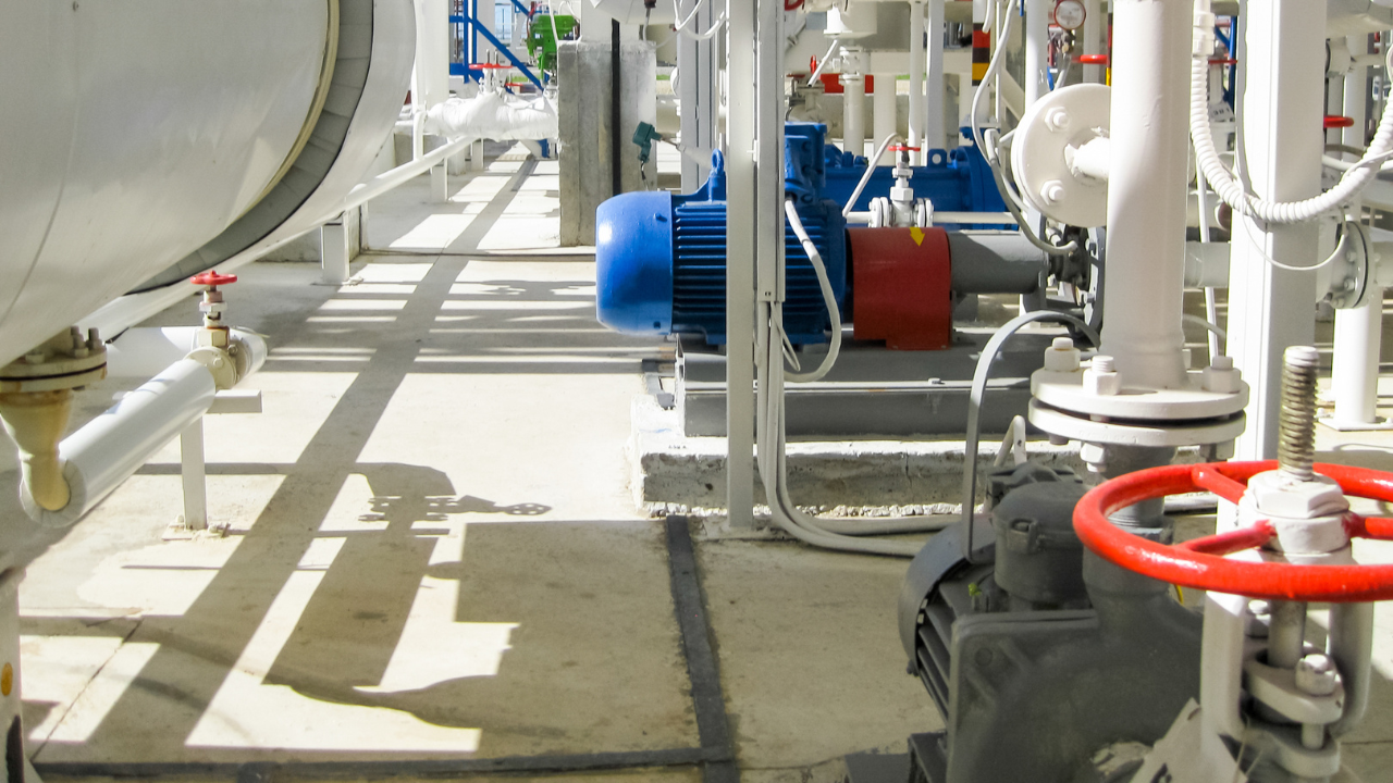
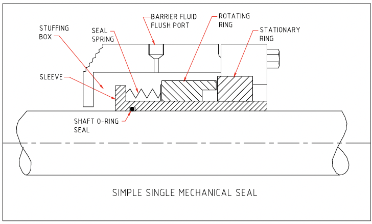
Consumers use the term "flushing" to describe six different methods of bringing fluid to the stuffing box area of a centrifugal pump. Experienced seal people use different terms to differentiate between the methods. Water is one of the best barrier or buffer fluids because of its high specific heat and good conductivity. Petroleum oil is probably one of the worse because of its low specific heat and poor conductivity. Keep this in mind when you select a barrier or buffer fluid for your seals.
Consumers use the term "flushing" to describe six different methods of bringing fluid to the stuffing box area of a centrifugal pump. Experienced seal people use different terms to differentiate between the methods. Water is one of the best barrier or buffer fluids because of its high specific heat and good conductivity. Petroleum oil is probably one of the worse because of its low specific heat and poor conductivity. Keep this in mind when you select a barrier or buffer fluid for your seals.
Get mechanical seals working properly. Mechanical seals are used to keep the bulk contents of rotating equipment such as pumps and compressors from escaping. They do this by sealing the shaft that protrudes from the casing. They require quality installation and operation conditions for a long life. Keywords: precision assembly, barrier fluid, stationary seal, rotary seal, alignment.
Get mechanical seals working properly. Mechanical seals are used to keep the bulk contents of rotating equipment such as pumps and compressors from escaping. They do this by sealing the shaft that protrudes from the casing. They require quality installation and operation conditions for a long life. Keywords: precision assembly, barrier fluid, stationary seal, rotary seal, alignment.
"What's the system's normal operating temperature? What's the system's usual operating pressure range?" If you can't answer these two basic questions about the vital signs of your hydraulic equipment I strongly recommend you make the effort to get to know your hydraulic equipment better. The information is easy to collect and can give valuable insight to the health of your hydraulic equipment.
"What's the system's normal operating temperature? What's the system's usual operating pressure range?" If you can't answer these two basic questions about the vital signs of your hydraulic equipment I strongly recommend you make the effort to get to know your hydraulic equipment better. The information is easy to collect and can give valuable insight to the health of your hydraulic equipment.
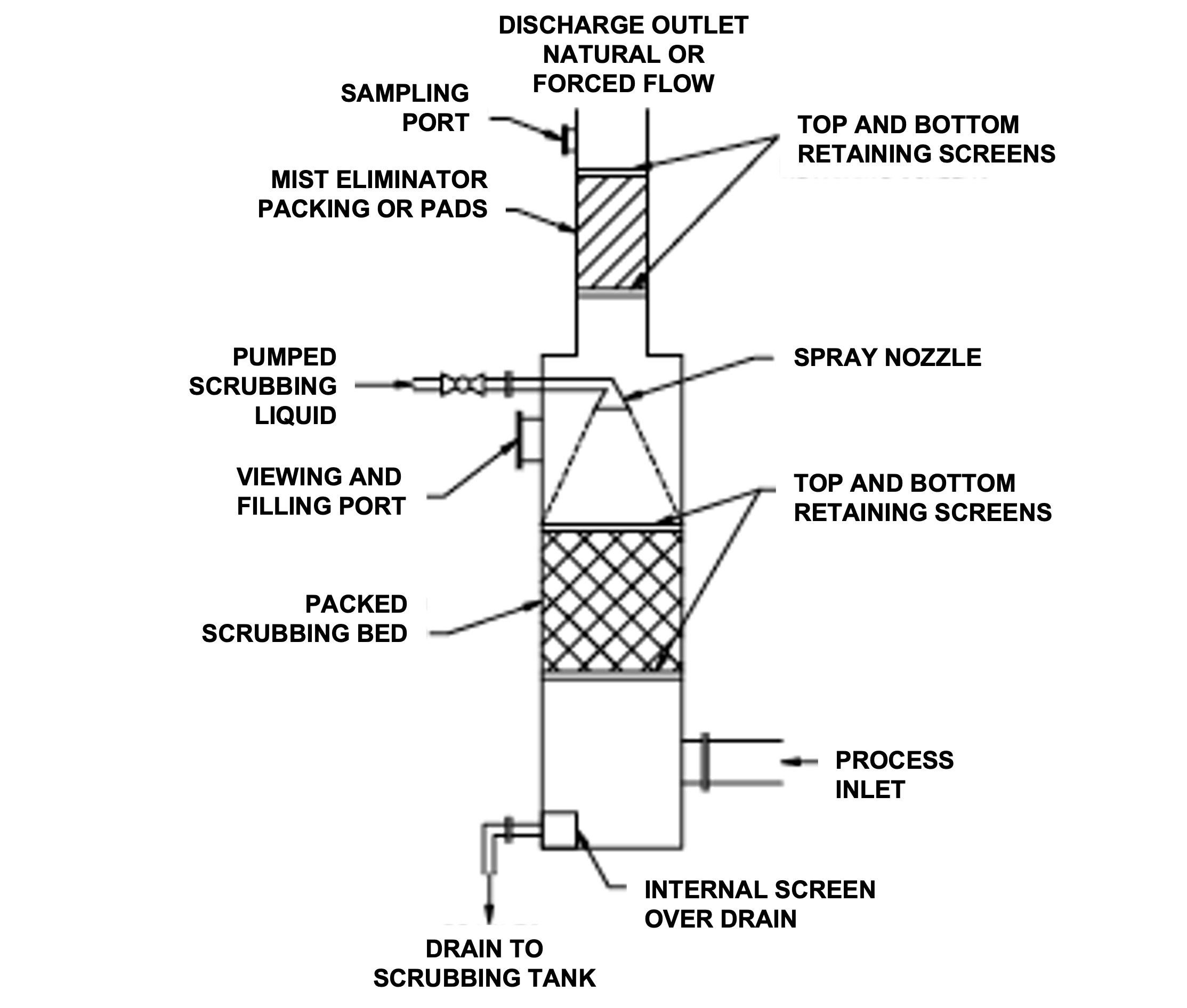
Is your scrubbing tower working? A wet scrubbing tower is used to clean odors, particles, mists, and vapors from a gas stream. The gas is forced through the tower. As it moves from inlet to outlet it is washed and cleaned. The washing is done with suitable chemicals that remove the active components in the gas flow. The gas is cleaned to environmentally acceptable levels and discharged to atmosphere.
Is your scrubbing tower working? A wet scrubbing tower is used to clean odors, particles, mists, and vapors from a gas stream. The gas is forced through the tower. As it moves from inlet to outlet it is washed and cleaned. The washing is done with suitable chemicals that remove the active components in the gas flow. The gas is cleaned to environmentally acceptable levels and discharged to atmosphere.
You may get the impression that implementing these steps will be costly and very difficult to achieve. The thing you need to bear in mind is: “You are already spending the money.” The only question is: “Are you getting the result from your pumping systems that you are looking for?” If you can create an environment that allows your entire team to become engaged in implementing these concepts, it will be the best investment you ever made.
You may get the impression that implementing these steps will be costly and very difficult to achieve. The thing you need to bear in mind is: “You are already spending the money.” The only question is: “Are you getting the result from your pumping systems that you are looking for?” If you can create an environment that allows your entire team to become engaged in implementing these concepts, it will be the best investment you ever made.