Hydraulic Testing & Diagnostics
Applied.com
The 7 Basic Steps of Hydraulic Testing & Diagnostics
Learn how to diagnose hydraulics so that your hydraulic testing can be focused on one or two components.
1. Know the System
In other words, “Do your homework.” Study the machine technical manuals. Know how the system works. Is it open or closed center? What should the valve settings and pump output be?
Keep up with the latest service bulletins. Read them and then file in a handy place. The problem on your latest machine may be in this month’s bulletin, giving the cause and remedy. You can be ready for any problem by knowing the system.
2. Ask the Operator
A good reporter gets the full story from a witness- the operator. He can tell you how the machine acted when it started to fail, what was unusual about it. Try to find out if any do-it-yourself service was performed. You may find that the problem is elsewhere, but you should know if any adjustments were tampered with.
3. Operate the machine
Get on the machine and operate it. Warm it up and put it through its paces. Don’t completely trust the operator’s story – check it for yourself. Are the gauges reading normal? If not, it may be hydraulic trouble or faulty gauges. How is the performance? Is the action slow, erratic, or nil? Do the controls feel solid or “spongy”? Do they seem to be “sticking”? Smell anything? Any signs of smoke? Hear any funny sounds? Where? At what speeds or during what cycles?
4. Inspect the Machine
Now get off the machine and make a visual check. Use your eyes, ears, and nose to spot any signs of trouble. First inspect the oil in the reservoir. How is the oil level? Is the oil foamy? Milky? Does it smell scorched? Does it appear to be too thin or too thick? How dirty is it? If the oil is very dirty, also check the filters for clogging.
Feel the reservoir and lines. Are they hotter than normal? Are they caked with dirt and mud? Is the paint peeled off from heat? Check the pump inlet line for restrictions. Check for collapsed hoses. Follow the circuit and keep on checking. Look for oil leaks at line connectors. Watch for air leaks at loose clamps, etc.
Check the oil cooler, is it free of trash and mud? Look closely at the components. Inspect for cracked welds hairline cracks, loose tie bolts, or damaged linkages. While you inspect, make a note of all the trouble signs.
5. List the Possible Causes
Now you are ready to make a list of the possible causes. What were the signs you found while inspecting the machine? And what is the most likely cause? Are there other possibilities? Remember that one failure often leads to another.
6. Reach a Conclusion
Look over your list of possible causes and decide which are most likely and which are easiest to verify. Use the Troubleshooting Charts at the end of this section as a guide. Reach your decision on the leading caused and plan to check them first.
7. Test Your Conclusion
Now for the final step: before you start repairing the system, test your conclusions to see if they are correct. Some of the items on your list can be verified without further testing. Analyze the information you already have.
Were all the hydraulic functions bad? Then probably the failure is in a component that is common to all parts of the system. Examples: pump, filters, system relief valves.
Was only one circuit bad? Then you can eliminate the system components and concentrate on the parts of that one circuit.
Testing the Machine
Now your list is beginning to narrow so that you can point your tests at one or two components. The next part of this chapter will tell you how to test the system and pinpoint these final troubles.
Testing with gauges or a hydraulic analyzer is the most effective way to pinpoint troubles in the system. However, here are some preliminary checks you can make without using a tester or prior to using one.
1. Checking for Leaks
If you suspect the control valve or cylinder is leaking, do the following:
• Raise the hydraulic equipment a few feet off the ground, return the control lever to neutral and shut off the engine.
• Notice whether the equipment settles toward the ground. If the equipment settles, temporarily support it and disconnect the return line between the control valve and reservoir, then plug the line (Figure D1).
• Remove the support and examine the open port in the control valve as the equipment settles. If oil leaks from the port, the control valve spool is leaking.
• If no oil is leaking from the control valve, check the cylinder as follows. Run the cylinder to one end of its stroke. Support the equipment if it is raised, then shut off the engine. Remove the hose from the end of the cylinder that was not pressurized (Figure D2).
• Start the engine again, pressurize the cylinder, and see if any oil comes out of the open port. Repeat the test in the opposite direction since it may be possible for the cylinder to leak in only one direction. If oil leaks out the open cylinder port, the seals on the piston must be replaced.
2. What a Hydraulic Tester Does
• If you cannot locate the trouble with the operational checks, check the system using a hydraulic analyzer or test gauges. Using this equipment, you can accurately measure oil flow, pressure, and temperature, and quickly isolate faulty components.
• Hydraulic analyzers are available with pressure loading valves, pressure gauges (high and low pressure), flow meters, and temperature gauges to precisely analyze a complex hydraulic system.
• In testing any hydraulic circuit, the following four checks are of prime importance:
Temperature – The oil should be checked for correct operating temperature to assure accuracy of the tests that follow.
Flow – The flow check determines if the pump is developing its rated output.
Pressure – Pressure checks test relief valves for proper operation. In a closed-center system, pressure checks indicate the operation of the main pump.
Leakage – The leakage test isolates leakage in a particular component.
These basic checks may be made with most hydraulic testers. Before beginning, however, read the instruction manual furnished with the tester and review the system. You should have a thorough knowledge of the machine’s specifications (relief valve pressures, pump output, engine rpm, and operating temperature) to accurately test the system.
To test a machine, you must disconnect some of the oil lines. But remember, DIRT IS THE WORST ENEMY OF A HYDRAULIC SYSTEM. Before disconnecting oil lines, steam clean the machine. And be sure to plug all openings to keep out the dirt.
3. Pump Testing
The pump is the generating force for the whole hydraulic system. This is the place to start testing the system.
Installing the Hydraulic Tester
• Relieve any pressure in the system and disconnect the pressure line between the pump and the control valve. Attach the pressure line to the hydraulic tester INLET port (Figure D3).
• Connect hydraulic tester OUTLET port to the reservoir. Whenever possible, connect directly to the reservoir return line because it usually has a return filter. On a closed-center system, always return hydraulic tester oil to a point between the main hydraulic pump and the charging pump to maintain pressure in the system (or to be sure the main pump does not lose its charge).
• Check the oil level and slowly close the tester load valve to load the system. Do not exceed the system’s rated pressure. Continue loading until the normal operating temperature of the system is reached.
Be sure the tester load valve is OPEN before starting any tests. The load valve can develop tremendous pressure on a component if it is closed too far.
Operating the Hydraulic Tester
• With the tester load valve open, record maximum pump flow at zero pressure.
• Slowly close the load valve to increase pressure and record the flow at 250 psi increments from zero pressure to maximum system pressure. Write down your test results so you can refer to them later.
• Open the hydraulic tester load valve until maximum pump flow is again at zero pressure.
• Shut off the engine/electric motor.
• Pump Test Diagnosis:
Pump flow at maximum pressure should be at least 75% of pump flow at zero pressure. If pump flow is poor during the free flow test as well as the pressure tests, the pump probably is not getting enough oil. This problem could be caused by low oil supply, air leaks, a restricted pump inlet line, or a dirty reservoir, filter or breather. If the pump tests okay, then start checking the system components for trouble.
4. System Testing
Installing the Hydraulic Tester
• Install a tee fitting in the line between the pump and the control valve and attach the hydraulic tester INLET port to this tee.
Leave the return line from the hydraulic tester OUTLET port connected in the same way as it was for the pump test.
Operating the Hydraulic Tester
• Open the hydraulic tester load valve.
• Start the electric motor or the engine and adjust it to the manufacturer’s recommended operating speed.
• Slowly close the hydraulic tester load valve to load the system. Continue loading the system until normal operating temperature is reached.
• Open load valve to record maximum system flow at zero pressure.
• Operate the control valve and hold it in one of its power positions.
• Slowly close the hydraulic tester load valve and record flow in 250 psi increments from zero pressure to maximum system pressure.
• Open the load valve until maximum flow is again at zero pressure and repeat the test in the rest of the control valve power positions.
Be sure to make all the tests at the same oil temperature to get readings that can be compared. If oil is too hot from the previous test, allow it to circulate through the system for cooling.
5. System Test Diagnosis
Here’s how to judge the system tests:
• If flow at each pressure is same as for pump test, all components are okay.
• If pressure begins to drop before full load is reached, one of the circuits is bad.
• The pressure drop is caused by leakage. To find out whether the leakage is in the control valve or the cylinder, disconnect the cylinder return line and move the control valve to a power position. If oil leaks from the cylinder return port, the cylinder is at fault and must be repaired. If no oil leaks out, the control valve is probably at fault.
• If flow drops the same with the control valve in all positions, the system relief valve is probably at fault. This condition could also indicate a leak in the control valve.
6. Relief Valve Diagnosis
• If equipment with circuit relief valves is being checked, you can tell when the valves open because flow will suddenly drop about 3 gpm (or drop to zero gpm if a full-flow relief valve is used). Often the relief valves will start to “crack” open before they reach their full pressure settings. This can be noted by comparing the pressure and flow rate readings made in the circuit test above. Any great decreases in flow rate in these valves indicates a faulty valve.
As a general rule: faulty SYSTEM relief valves will affect readings in all tests. Faulty CIRCUIT relief valves will affect only pressure readings in the individual circuits.
Reading up on your hydraulic system? Click here to learn some preventative maintenance tips.
Related Articles
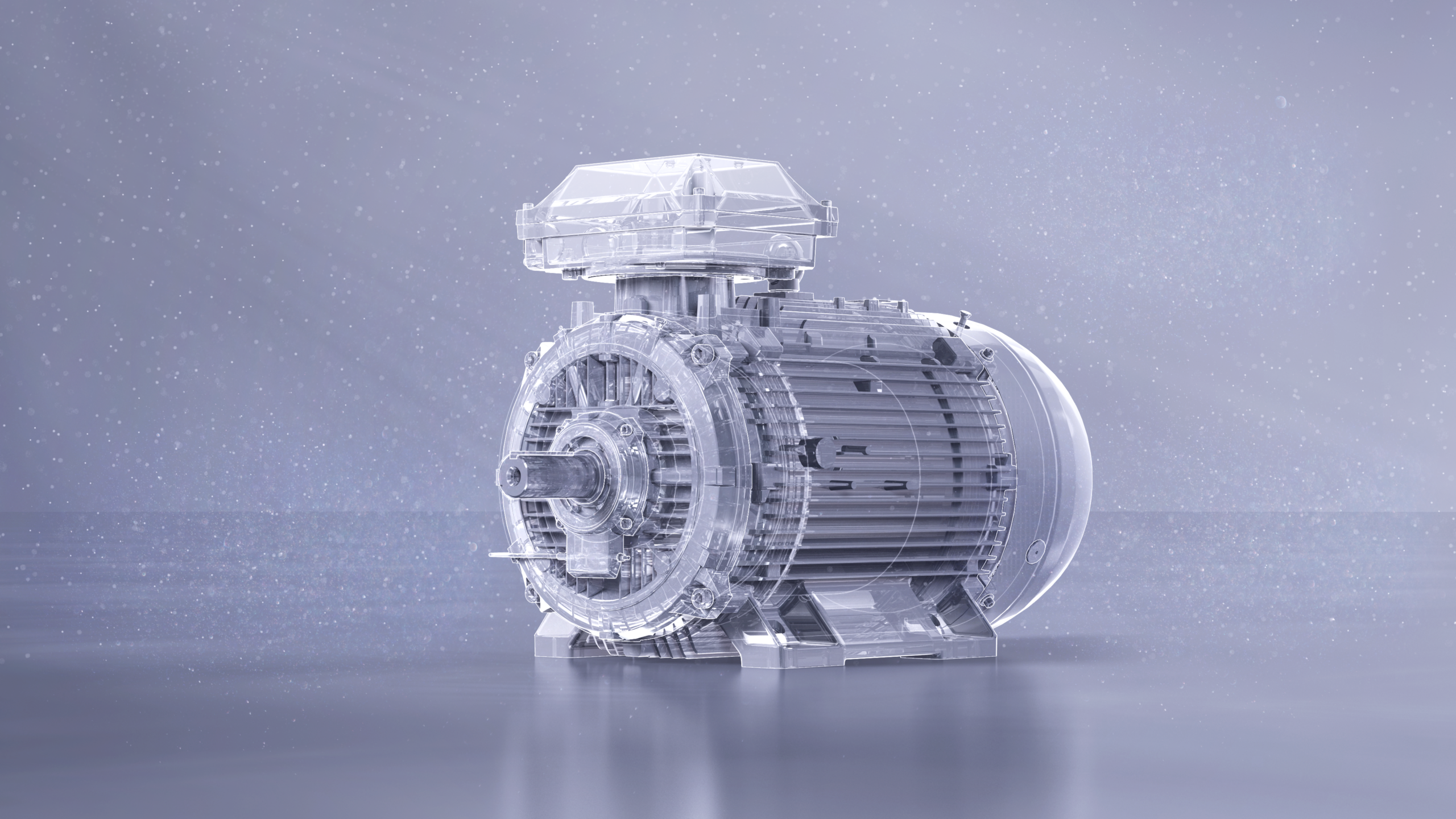
High-efficiency SynRM motors, a game changer in potentially explosive environments

7 Costly Causes of Nozzle Wear

Electrical Corona & Testing
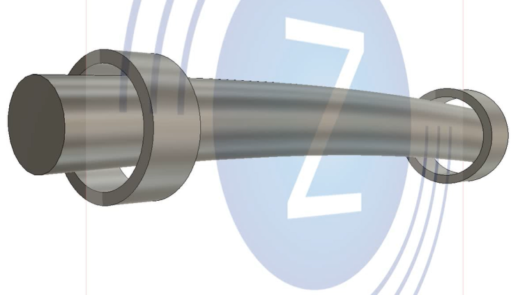
Diagnosing a Bent Shaft
Spherical Roller Bearings Preventive Maintenance
What is Wrong with the Modern Centrifugal Pump?