Factors which Influence the Speed of an Air Cylinder
Womack
This subject, about speed of an air cylinder, will be covered in two parts: (1), those factors to be considered when first designing the system and selecting cylinder bore diameter and, (2), changes which can be made in an existing system to increase cylinder speed.
It is very difficult to calculate and predict the speed of an air cylinder; there are too many variables which influence speed and on which it is difficult to gather accurate data. We must rely mainly on good design practices and use the benefit of past experience. It is better to have the cylinder speed too fast to begin with because it can always be reduced with a speed control valve, but if it is too slow to begin with, it is more difficult to increase its speed later.
Factors to be Considered on Original Design
A. Supply Air Pressure. A knowledge of the pressure level available for the machine is important. If the air pressure may fluctuate during the day, the system pressure regulator cannot, of course, be set higher than this, and this low level should be taken as the design pressure level for sizing the cylinder piston area. The design pressure must be considerably higher than the pressure needed to move the load (with the cylinder selected) because a substantial part of it will be lost through line and valve flow resistance as soon as the cylinder starts to move. Figure 1 indicates the important circuit points where pressure loss will occur.
B. Piping and Valve Size. Any flow resistance in piping and valving reduces cylinder speed. For high speed this resistance must be held to a minimum.
A rule-of-thumb says that for moderate cylinder speed, the flow area through piping and valving should be at least equal to the flow area through the cylinder ports; perhaps a pipe size larger if very high speed is required. Usually for cylinders up to and including 3-inch bore, a 1/4 or 3/8″ size valve is sufficient for normal cylinder speed.
Of course if two cylinders are operated from one valve, the piping and valve size should be increased to twice the internal area that would be used to operate a single cylinder.
C. Cylinder Piston Area. The cylinder selected must have sufficient piston area to match load resistance at a pressure substantially less than maximum line pressure. Rules for oversizing piston area are given later.
Typical Compressed Air System
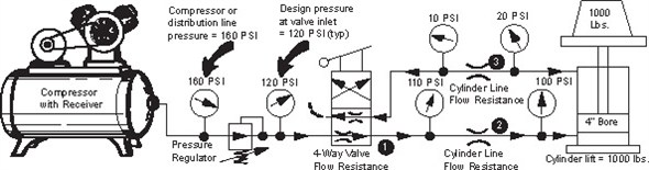
Figure 1. The air flow path through a cylinder and its 4-way valve is shown. Points 1, 2, and 3 show where pressure is lost. These losses occur only while air is flowing, and the greater the air flow, the higher the pressure losses. The amount of flow loss in the circuit largely determines the maximum speed at which the cylinder piston can travel.
The design pressure for an air system can be taken as the gauge pressure on the 4-way valve inlet, which is the pressure to which the system pressure regulator has been set, 120 PSI in this figure. Pressure gauges installed at appropriate points in the flow path illustrate the pressure losses occurring in the circuit while the cylinder is moving.
Since the piston area of the 4″ bore cylinder is 12.57 sq. ins., it will require 80 PSI to exactly balance the 1,000 lb. load resistance (12.57 × 80 PSI = 1,000 lbs.). Additional pressure will be required to move it. This 80 PSI must be differential pressure across the cylinder ports, not the gauge reading at the blind end port. In this figure the differential pressure is shown as 100 PSI on the blind end port minus 20 PSI on the rod end port.
For the cylinder piston to move, air must circulate through the system, and flowing air produces pressure losses. The cylinder, after starting out, will accelerate to the speed where the sum of all flow losses plus the 80 PSI pressure required to balance the load equals the input pressure of 120 PSI. It cannot travel faster because a higher flow of air would produce flow losses greater than the available inlet pressure. To increase cylinder speed, some of the flow resistance must be reduced or eliminated.
Quick Exhaust Valves
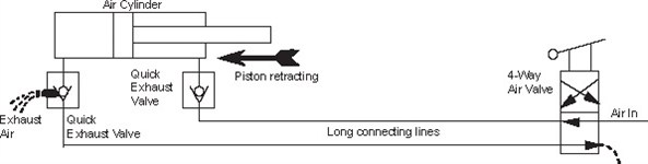
Figure 2. Quick exhaust valves may be used with either single-acting or double-acting cylinders. They increase cylinder speed by eliminating most of the back pressure of the exhaust air, permitting it to vent directly to atmosphere. They are particularly helpful in applications where the lines connecting valve and cylinder are unusually long.
On-double-acting cylinders install the quick exhaust valve directly at the cylinder port which is exhausting, using a close nipple. If high speed is wanted in both directions, install a valve at each cylinder port. A 1/4 or 3/8″ size is usually large enough for up to 3″ bore cylinders.
How to Increase Speed of an Air Cylinder
On an existing system where the air cylinder moves too slowly, one or more of these suggested remedies should be tried. Note: They are not applicable for hydraulic cylinders.
- Increase air PSI, if possible, at the inlet of the 4-way valve by increasing the adjustment on the system pressure regulator. This will cause a higher rate of air flow into the cylinder, increasing its speed.
- If an exhaust muffler is used, remove and discard. it or replace it with a larger size.
- Remove speed control valves completely from the system. Their internal orifices are smaller than the line size, and even when wide open they add restriction both in the “free flow” and the “controlled flow” directions. If necessary to have speed controls, use models of one or two pipe sizes larger than line size, with reducing bushings to connect into the lines.
- Replace lines connecting cylinder to valve with larger hose or pipe. Supply lines may also be enlarged.
- Shorten hose lines and reduce the number of bends. All hose fittings and hose barbs have restricted flow. Eliminate unnecessary fittings. Enlarge lines to next larger hose size, using reducing couplings to connect into valve and cylinder portholes.
- Install a quick exhaust valve directly at the cylinder port which is exhausting for the cylinder direction in which a speed increase is needed.
- Replace the 4-way valve with one of higher flow rating.
- As a last resort, replace the cylinder with one having a larger piston area.
Rule-of-Thumb: Selection of Cylinder Piston Area
The cylinder piston must have an area large enough to produce the required force at considerably less PSI than is available at the 4-way valve inlet, because not all of this pressure will reach the piston. On average applications, a moderate speed will result if the piston area is oversized about 25%. If high speed is especially important, the piston area should be about twice the area needed just to equal the load resistance. This should leave suficient pressure to satisfy flow resistance of lines and valves.
Measurement of Peak Pressures in a Hydraulic Circuit
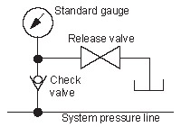
Simple instrumentation for measuring peak pressure developed in a hydraulic circuit due to shocks of various kinds, consists of an ordinary pressure gauge plus a check valve and release valve. The gauge should be subjected to a number of pressure pulses over a short period until trapped pressure in the gauge does not rise further. The gauge should have arrange of two to three times the normal system pressure. The check and release valves should be leaktight models having soft seals. All air must be purged from the gauge before starting a measurement, and it may help to have the gauge lying flat or mounted upside down.
© 1988 by Womack Machine Supply Co. This company assumes no liability for errors in data nor in safe and/or satisfactory operation of equipment designed from this information.This idea was suggested by Mr. William R. Dollase in Hydraulics & Pneumatics magazine. As far as measurement of peak pressures, he claims the accuracy compares favorably with oscilloscope and strain gauge measurement, although for wave shape, rise and decay time, and overshoot, the more expensive instrumentation must be used.
Related Articles

OEE: Overall Equipment Effectiveness
Chain Drive Design Recommendations

Matching a Hydraulic Motor to the Load
Cavitation
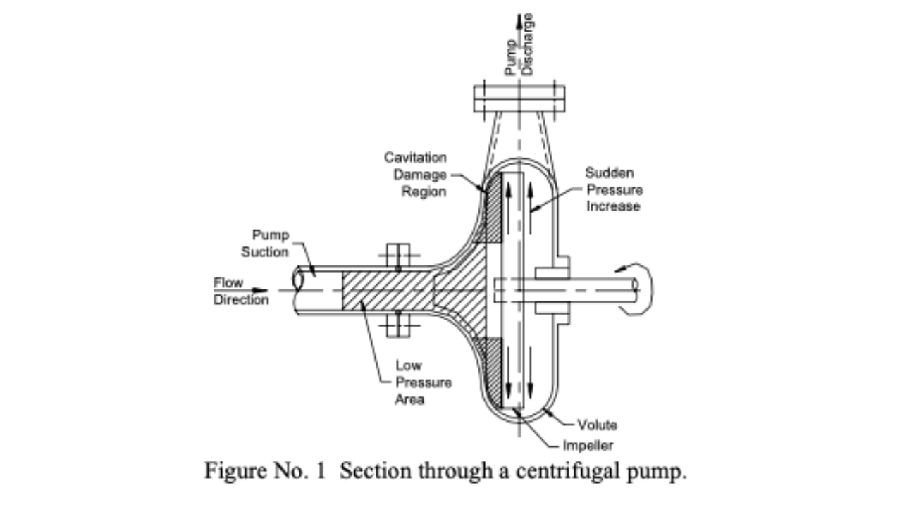
The Pump Impeller: Pump Life Extension