What is Wrong with the Modern Centrifugal Pump?
www.mcnallyinstitute.com
Ask for a modern centrifugal pump recommendation from your favorite supplier and chances are he will recommend one of the standard pump designs that conform to either the A.N.S.I., I.S.O. or D.I.N. specifications. On the surface that might seem like a good recommendation, but the fact is that all of these designs will cause you maintenance problems.
Please refer to the following illustration. I have pictured some of the more obvious problems that we find with these designs.
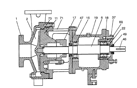
The Impeller is Too Far Away From the Bearings
The modern centrifugal pump was designed for packing and that is where the problem starts. To produce enough axial space to accommodate at least five rings of packing (any less would cause sealing problems), a lantern or lubricating ring, a gland to tighten the packing and enough room to get your hands in there, the manufacturer had to move the pump impeller too far away from the bearings. He is depending upon the packing to act as part of the bearing system, especially at start up when the shaft is subjected to its maximum radial deflection.
Impeller imbalance, vibration, misalignment, pipe strain, cavitation, critical speeds, and other forms of shaft deflection add to the existing problem, causing excessive movement of the mechanical seal components.
If the modern centrifugal pump had been designed for a mechanical seal the impeller would have been positioned closer to the bearings saving considerable initial investment cost (short shafts cost less money). This was not done, however, and so the seal is jammed into the small radial space provided for the packing.
In Most Cases a Sleeve Was Installed on the Shaft
The shaft diameter was reduced to accommodate the sleeve and this compounded the problem. Sleeves are installed for several reasons:
- To provide corrosion resistance when building the shaft of corrosion resistant material would be too costly.
- To provide a wear surface for packing and those seals that frett or damage shafts.
- To position an impeller
- Some seal manufacturers use the sleeve as a convenient method of attaching a metal bellows seal to the shaft.
In ninety percent of the cases the second reason is why most manufacturers use shaft sleeves. To evaluate the relationship between shaft diameter and length, familiarize yourself with the concept of L3/D4 that was explained in several of the earlier papers published in this series.
The Stuffing Box Inside Diameter is too Small
The stuffing box cross section was narrowed to about 3/8 inch (10 millimeter) to accommodate small cross section packing. In the smaller shaft sizes the cross section is 5/16″ (8 mm.). This narrow space does not give the seal enough room to utilize centrifugal force to throw solids away from the lapped seal faces, or provide enough clearance for adequate cooling of the components and sealing fluid. This has caused many customers to provide expensive and unreliable flushing that could be eliminated in many instances, if there was adequate room between the seal and the inside wall of the stuffing box.
The Stuffing Box is Too Long
The length was added to accommodate all the rings of packing and the lantern ring. Recognizing this length as a problem the manufacturer did not leave enough room between the face of the stuffing box and the first obstruction, to accommodate some of the modern cartridge double seals or the newest split mechanical seals.
There is No Double Volute to Prevent Radial Loading of the Impeller
This has caused customers to install inefficient “by pass” lines to prevent shaft breakage and seal damage at start up or when running too far off of the best efficiency point of the modern centrifugal pump.
Most of These Pumps are of the Back Pull Out Design
This means that the wet end is left on the piping and the power end along with the adapter are brought back to the shop for seal replacement and repair. Unless you have a seal cartridge mounted, or you are using a split seal design, you will have trouble making an initial impeller adjustment with most of the open impeller designs in use today. The direction of adjustment varies with manufacturers.
The Impeller Adjustment is Almost Always Made From the Bearing End of the Pump
This means that to compensate for wear (a very common problem when pumping abrasives) the shaft has to be moved either towards the front of the pump volute or, as in the case of the Durco pump, back towards the back plate. This movement can be as much as a total of .250 inches (6 millimeter). In either case the seal setting is disturbed and short seal life follows. Most plants have both types of designs that causes confusion with the mechanics.
The Wrong Mechanical Seals are being Supplied by the Pump Manufacturer
Unless you have specified a particular seal brand and model number the seals are always unbalanced designs with unknown grades of materials, having very limited application and causing a profusion of spare parts.
Most original equipment manufacturer (O.E.M.) seals will damage shafts (fretting) causing the use of shaft sleeves that will weaken the shaft and raise the L3/D4 number above 60 (2 mm. the metric system)
“C” or “D” Frame Adapters are not being Provided as Standard Equipment
Although not available for every pump, these adapters can be used to eliminate the need for time consuming and costly alignment procedures. None of the popular modern centrifugal pumps are equipped with jack bolts to facilitate the manual alignment and this just compounds the problem. The result is that we find alignment not being done at all in some cases, and done poorly in others, The excuse is always the same, “There is no time to do it correctly”. The result is poor seal and bearing performance.
Lip of Grease Seals are Being Provided to Protect the Bearings from Water Getting In and Destroying the Lubrication
These lip seals have a design life of less than two thousand hours (three months) and will damage the expensive shaft, as they remove the protective oxide layer. All pump manufacturers recognize the short life problem and they install a small rubber ring outboard of the lip seal to try to deflect the water or chemical away from the bearings.
Water ingestion is a major cause of bearing failure. Liquid enters the bearing through the lip seals from three different sources:
- Packing leakage
- From the water hose that is used to wash away packing leakage.
- From the atmosphere (aspiration) when the pump stops and the bearing case cools down. As much as 16 ounces (0,5 liters) of air is expelled from the pump as its’ temperature increases from ambient to operating . This moisture laden air returns through the vent or lip seals as the bearing case cools down at pump shut off.
The problem with water ingestion can easily be solve by replacing the lip seals with mechanical face seals and providing an expansion chamber on the bearing case. Labyrinth seals are another solution although they are not as totally effective as face seals. Neither the labyrinth seals nor the face seals should cause fretting problems at the bearing location.
The Bearing Lubrication System is Poorly Designed
- The oil level must be located half way through the lower ball of the bearings when the pump is shut off. You need a good sight glass to see this location. Most pumps do not have a proper sight glass and an oiler doesn’t make any sense since there is no place for the oil to go, and it cannot wear out.
- Greased bearings applications have no protection to prevent over greasing. The recommended greasing procedures generally are not followed
- An oil mist system would be the best if you could solve the problem of leakage of the mist to atmosphere and the resultant fugitive emissions problems.
- If you open the bearing case of your spare power ends you will find that the inside of the case is often badly rusted. The manufacturer should have provided some type of a protective coating to prevent this problem. If you elect to provide your own coating (and you should) be careful about using synthetic oils for your bearing lubrication. They contain strong detergents and can remove many of these protective coatings.
A Recirculation Line has been Installed from the Discharge Side of the Pump Back to the Stuffing Box
Many liquids contain solids. Centrifugal force will throw these solids against the inner wall of the volute and out this recirculation line. They will then enter into the stuffing box at high velocity, causing premature seal failure.
In most cases the problem can be solved by eliminating this line and connecting a new line from the bottom of the stuffing box to the suction side of the pump. This will recirculate fluid from behind the impeller, (where it is much cleaner) through the stuffing box, and back to the suction side.
- CAUTION do not connect to the suction side if you are pumping the fluid at or near its vapor point. It could flash in the stuffing box. This system is not as effective if you are using an open impeller design that adjust towards the back plate (Durco as an example)
The Thrust Bearing is Being Retained by a Simple Snap Ring
Up to 65% of its efficiency most centrifugal pumps thrust towards the thrust bearing, but between 65% and 100% of the pumps efficiency (the normal running mode) the thrust is towards the pump volute and this means that the simple snap ring is carrying the whole load. This is the reason we see so many bent and broken snap rings. A more positive retaining system is needed.
The Wet End is not a Center Line Design
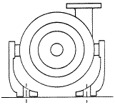
The above illustration explains the centerline concept. This design will compensate for metal expansion at the wet end of the pump. It should be specified every time the pumping temperature exceeds 200° F (100° C).
Note that the volute is being supported on its sides. This will allow thermal growth to take place both up and down eliminating a great deal of suction pipe strain, wear ring damage and subsequent seal misalignment at the stuffing box face.
Related Articles
Hydraulic System FMEA Made Easy
The 7 Secrets of Pump Reliability

Spooky Sounds in the Haunted Factory

PLC: Programming in List on a Mitsubishi PLC – Part 1

Stress in Metals Causes Failure