[webinar] Embracing Digital Transformation in Maintenance & Plant Operations | March 13 at 10AM EST – Register Now
A Guide to Matching Electric Motors with Hydraulic Power Units
A Guide to Matching Electric Motors with Hydraulic Power Units
Ronald R. Gould, CFPE
Sizing electric motors correctly for hydraulic power units can save a sizable amount of money over the life of the equipment. If system pressure and flow are constant, motor sizing simply boils down to the standard equation:
hp = QP / 1714EM
where: hp is horsepower Q is flow in gpm P is pressure in psi, and EM is pump’s mechanical efficiency.
However, if the application requires different pressures during different parts of the operating cycle, you often can calculate root mean square (rms) horsepower and select a smaller, less-expensive motor. Along with the calculation of rms horsepower, the maximum torque required at the highest pressure level of the application also must be found. Actually the two calculations are quite simple.
For example, such an application might use a 6-gpm, 3450-rpm gear pump to power a cylinder linkage that operates for an 85-sec cycle. The system requires 3000 psi for the first 10 sec, 2200 psi for the next 30 sec, 1500 psi for the next 10 sec, and 2400 psi for the next 10 seconds. The pump then coasts at 500 psi for 20 sec, followed by 15 sec with the motor off.
It’s tempting to use the standard formula, plug in the highest-pressure segment of the cycle, and then calculate:
hp = (6)(3000) / (1714)(0.9) = 11.7 hp for 10 sec.
To provide this horsepower, some designers would choose a 10-hp motor; others would be ultra-conservative and use a 15-hp motor; a few might take a chance with 7.5 hp. These motors in open drip-proof C-face models with feet would list at about $570, $800, and $400 respectively, so there could be savings of $170 to $400 per power unit by choosing the 7.5-hp motor – if it will do the job.
To determine this, first calculate the horsepower for each pressure segment of the cycle:
hp1 = 6(2200) / (1714)(0.9) = 8.5 hp for 30 sec. hp2 = 6(1500) / (1714)(0.9) = 5.8 hp for 10 sec. hp3 = 6(500) / (1714)(0.9) = 1.9 hp for 30 sec.
The rms horsepower is calculated by taking the square root of the sum of these horsepowers squared, multiplied by the time interval at that horsepower, and divided by the sum of the times plus the term (toff /F), as indicated in the box at the bottom of this page.
Substituting the example values into the boxed equation and solving reveals that hprms equals 7.2. Thus, a 7.5-hp motor can be used from the standpoint of horsepower alone. However the second item, maximum torque, still must be checked before reaching a final decision. The maximum torque required to drive this particular pump will be found at the highest pressure – because the gear pump’s output flow is constant. Use this equation:
T = DP / (12)(6.28)EM
where: T is torque in ft-lb, and D is displacement in in.3
For this example, D = (6)(231) / (3450) = 0.402 in.3 Then T = (0.402)(3000) / (12)(6.28)(0.9) = 17.8 ft-lb.
Because electric motors running at 3450 rpm generate 1.5 ft-lb per hp, the 17.8 ft-lb of torque requires (17.8 / 1.5) or 11.9 hp at 3000 psi. This checks out closely enough for the example application. (At other standard motor speeds: 1725 rpm generates 3 ft-lb per hp; 1150 rpm, 4.5 ft-lb per hp; 850, 6 ft-lb per hp.)
Now the second criteria can be checked against what the suggested motor can deliver in torque. What is the pull-up torque of the 7.5-hp motor selected? Because the torque is least as the motor accelerates from 0 to 3450 rpm, it must be above 11.9 ft-lb with an acceptable safety margin. Note that a motor running 10% low on voltage will produce only 81% of rated pull-up torque: i.e., (208/230)2 = 0.81. Reviewing motor manufacturers’ performance curves will show several available 7.5-hp models with higher pull-up torque. Any of these motors could be a good choice for this application.
Both motor criteria now have been verified to match the motor with the appropriate hydraulic power unit. The rms horsepower is equal to or less than the rated motor’s horsepower. The motor’s pull-up torque is greater than the maximum required.
Machine conditions change from the time the machine is off line to when it is running under normal operating conditions. Some of these changes are due to process forces (e.g., fluid pressures, airflow, etc.). The most notable of these changes is the change in the temperature of the machine bearings and supports. This is called the machine's thermal growth.
Machine conditions change from the time the machine is off line to when it is running under normal operating conditions. Some of these changes are due to process forces (e.g., fluid pressures, airflow, etc.). The most notable of these changes is the change in the temperature of the machine bearings and supports. This is called the machine's thermal growth.
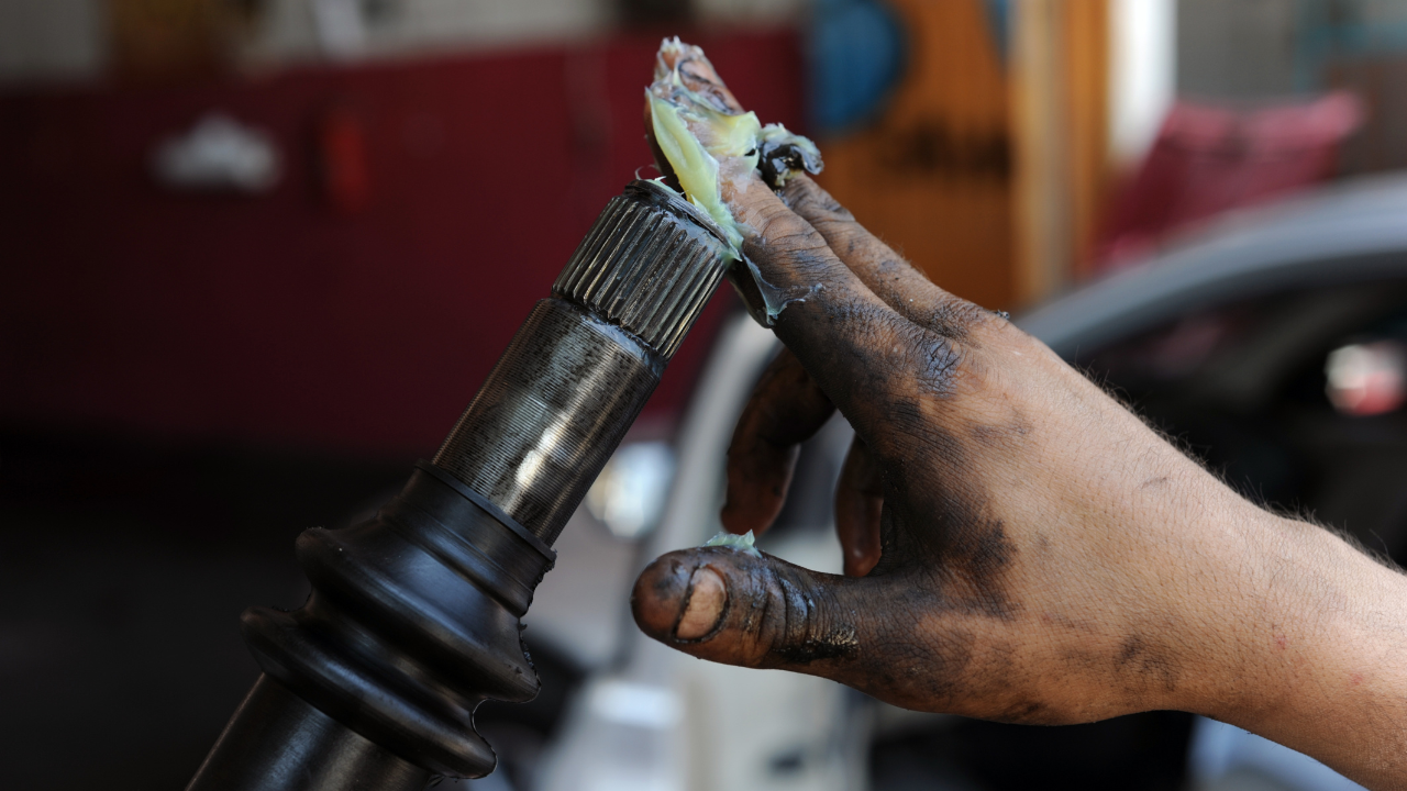
Gear pumps are the most common type of positive displacement pump, ideal for transferring high viscosity fluids such as automotive oils, plastics, paint, adhesives, and soaps. As with any pump, proper operation and regular maintenance are vital to reducing costly pump repairs and maximizing pump efficiency. Below are helpful tips for operating your gear pump and ensuring it achieves a long operating life through regular maintenance. As with any pump, proper operation and regular maintenance are vital to reducing costly pump repairs and maximizing pump efficiency.
Gear pumps are the most common type of positive displacement pump, ideal for transferring high viscosity fluids such as automotive oils, plastics, paint, adhesives, and soaps. As with any pump, proper operation and regular maintenance are vital to reducing costly pump repairs and maximizing pump efficiency. Below are helpful tips for operating your gear pump and ensuring it achieves a long operating life through regular maintenance. As with any pump, proper operation and regular maintenance are vital to reducing costly pump repairs and maximizing pump efficiency.
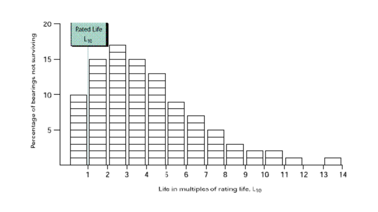
Bearing life is defined as the length of time, or the number of revolutions, until a fatigue spall of a specific size develops. This spall size, regardless of the size of the bearing, is defined by an area of 0.01 inch2 (6 mm2). This life depends on many different factors such as loading, speed, lubrication, fitting, setting, operating temperature, contamination, maintenance, plus many other environmental factors. Due to all these factors, the life of an individual bearing is impossible to predict precisely.
Bearing life is defined as the length of time, or the number of revolutions, until a fatigue spall of a specific size develops. This spall size, regardless of the size of the bearing, is defined by an area of 0.01 inch2 (6 mm2). This life depends on many different factors such as loading, speed, lubrication, fitting, setting, operating temperature, contamination, maintenance, plus many other environmental factors. Due to all these factors, the life of an individual bearing is impossible to predict precisely.
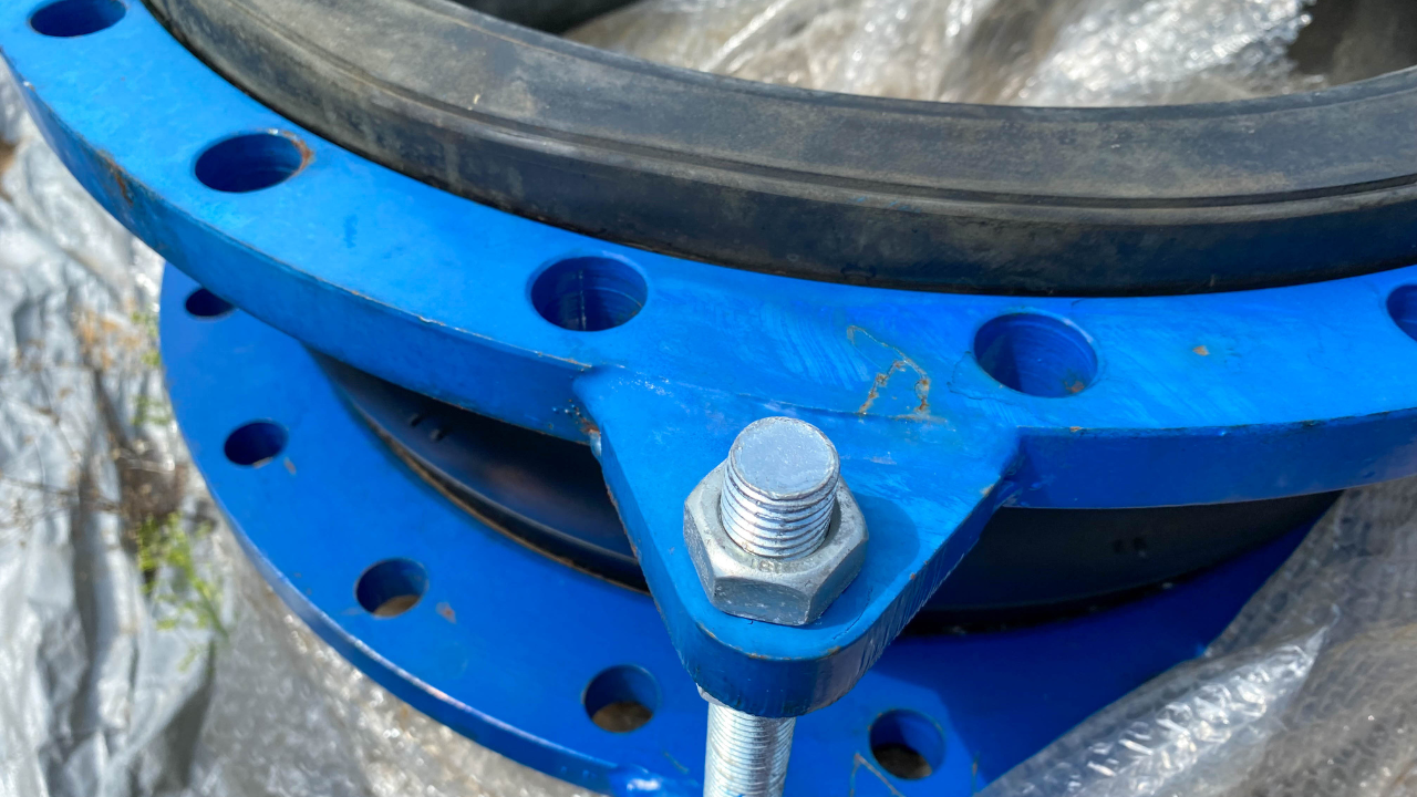
Expansion joints for pipework are often made from corrugated metal, especially when handling liquids or for operating pressures significantly above atmospheric. Metal expansion joints are outside the scope of the ESA guide.
Expansion joints for pipework are often made from corrugated metal, especially when handling liquids or for operating pressures significantly above atmospheric. Metal expansion joints are outside the scope of the ESA guide.
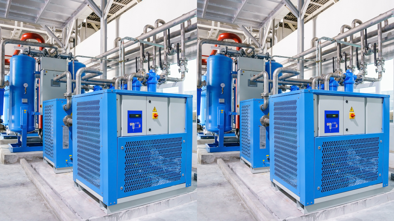
For many applications, a REFRIGERATED COMPRESSED AIR DRYER is one of your best solutions to getting the moisture out of your compressed air system. Look for these symptoms to tell when you need a Refrigerated Compressed Air Dryer...
For many applications, a REFRIGERATED COMPRESSED AIR DRYER is one of your best solutions to getting the moisture out of your compressed air system. Look for these symptoms to tell when you need a Refrigerated Compressed Air Dryer...
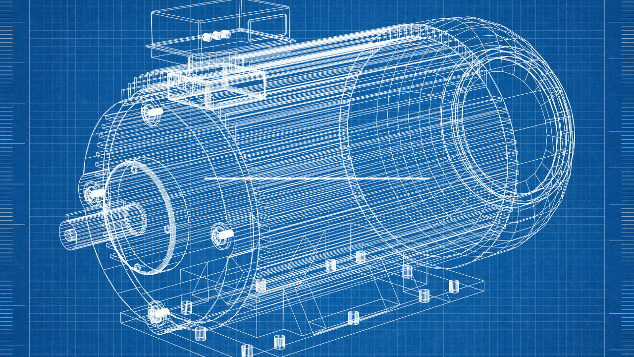
It is estimated that almost half (45 percent) of global electricity is used by electric motors. Electric motors drive a considerable amount of equipment in almost all industries, from power generation to water and food supply to consumer products. The importance of electric motors in modern society cannot be understated. It is because of this vital role that it pays huge dividends to keep your electric motors running efficiently through a quality reliability program that includes energized and de-energized electric motor testing (EMT).
It is estimated that almost half (45 percent) of global electricity is used by electric motors. Electric motors drive a considerable amount of equipment in almost all industries, from power generation to water and food supply to consumer products. The importance of electric motors in modern society cannot be understated. It is because of this vital role that it pays huge dividends to keep your electric motors running efficiently through a quality reliability program that includes energized and de-energized electric motor testing (EMT).
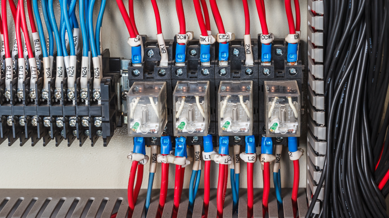
Last time, we pretty much ignored ladder diagrams. This time I'm giving you lots of them. We'll look at the ins and outs of turning those pretty pictures into powerful text. You'll gain insight into the block commands and the various structures that can be built using List. You'll leave with full knowledge of the perils and pitfalls.
Last time, we pretty much ignored ladder diagrams. This time I'm giving you lots of them. We'll look at the ins and outs of turning those pretty pictures into powerful text. You'll gain insight into the block commands and the various structures that can be built using List. You'll leave with full knowledge of the perils and pitfalls.