[webinar] Embracing Digital Transformation in Maintenance & Plant Operations | March 13 at 10AM EST – Register Now
A Guide to Matching Electric Motors with Hydraulic Power Units
A Guide to Matching Electric Motors with Hydraulic Power Units
Ronald R. Gould, CFPE
Sizing electric motors correctly for hydraulic power units can save a sizable amount of money over the life of the equipment. If system pressure and flow are constant, motor sizing simply boils down to the standard equation:
hp = QP / 1714EM
where: hp is horsepower Q is flow in gpm P is pressure in psi, and EM is pump’s mechanical efficiency.
However, if the application requires different pressures during different parts of the operating cycle, you often can calculate root mean square (rms) horsepower and select a smaller, less-expensive motor. Along with the calculation of rms horsepower, the maximum torque required at the highest pressure level of the application also must be found. Actually the two calculations are quite simple.
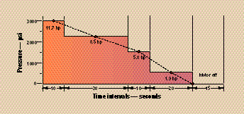
For example, such an application might use a 6-gpm, 3450-rpm gear pump to power a cylinder linkage that operates for an 85-sec cycle. The system requires 3000 psi for the first 10 sec, 2200 psi for the next 30 sec, 1500 psi for the next 10 sec, and 2400 psi for the next 10 seconds. The pump then coasts at 500 psi for 20 sec, followed by 15 sec with the motor off.
It’s tempting to use the standard formula, plug in the highest-pressure segment of the cycle, and then calculate:
hp = (6)(3000) / (1714)(0.9) = 11.7 hp for 10 sec.
To provide this horsepower, some designers would choose a 10-hp motor; others would be ultra-conservative and use a 15-hp motor; a few might take a chance with 7.5 hp. These motors in open drip-proof C-face models with feet would list at about $570, $800, and $400 respectively, so there could be savings of $170 to $400 per power unit by choosing the 7.5-hp motor – if it will do the job.
To determine this, first calculate the horsepower for each pressure segment of the cycle:
hp1 = 6(2200) / (1714)(0.9) = 8.5 hp for 30 sec. hp2 = 6(1500) / (1714)(0.9) = 5.8 hp for 10 sec. hp3 = 6(500) / (1714)(0.9) = 1.9 hp for 30 sec.
The rms horsepower is calculated by taking the square root of the sum of these horsepowers squared, multiplied by the time interval at that horsepower, and divided by the sum of the times plus the term (toff /F), as indicated in the box at the bottom of this page.
Substituting the example values into the boxed equation and solving reveals that hprms equals 7.2. Thus, a 7.5-hp motor can be used from the standpoint of horsepower alone. However the second item, maximum torque, still must be checked before reaching a final decision. The maximum torque required to drive this particular pump will be found at the highest pressure – because the gear pump’s output flow is constant. Use this equation:
T = DP / (12)(6.28)EM
where: T is torque in ft-lb, and D is displacement in in.3
For this example, D = (6)(231) / (3450) = 0.402 in.3 Then T = (0.402)(3000) / (12)(6.28)(0.9) = 17.8 ft-lb.
Because electric motors running at 3450 rpm generate 1.5 ft-lb per hp, the 17.8 ft-lb of torque requires (17.8 / 1.5) or 11.9 hp at 3000 psi. This checks out closely enough for the example application. (At other standard motor speeds: 1725 rpm generates 3 ft-lb per hp; 1150 rpm, 4.5 ft-lb per hp; 850, 6 ft-lb per hp.)
Now the second criteria can be checked against what the suggested motor can deliver in torque. What is the pull-up torque of the 7.5-hp motor selected? Because the torque is least as the motor accelerates from 0 to 3450 rpm, it must be above 11.9 ft-lb with an acceptable safety margin. Note that a motor running 10% low on voltage will produce only 81% of rated pull-up torque: i.e., (208/230)2 = 0.81. Reviewing motor manufacturers’ performance curves will show several available 7.5-hp models with higher pull-up torque. Any of these motors could be a good choice for this application.
Both motor criteria now have been verified to match the motor with the appropriate hydraulic power unit. The rms horsepower is equal to or less than the rated motor’s horsepower. The motor’s pull-up torque is greater than the maximum required.
The article is intended to provide a few tips for blower maintenance to plant maintenance professionals in reducing the downtime and increasing the reliability of blowers. Generally the apparent reasons for blower failure are: Failure of Bearings and High Vibrations
The article is intended to provide a few tips for blower maintenance to plant maintenance professionals in reducing the downtime and increasing the reliability of blowers. Generally the apparent reasons for blower failure are: Failure of Bearings and High Vibrations
It is estimated that almost half (45 percent) of global electricity is used by electric motors. Electric motors drive a considerable amount of equipment in almost all industries, from power generation to water and food supply to consumer products. The importance of electric motors in modern society cannot be understated. It is because of this vital role that it pays huge dividends to keep your electric motors running efficiently through a quality reliability program that includes energized and de-energized electric motor testing (EMT).
It is estimated that almost half (45 percent) of global electricity is used by electric motors. Electric motors drive a considerable amount of equipment in almost all industries, from power generation to water and food supply to consumer products. The importance of electric motors in modern society cannot be understated. It is because of this vital role that it pays huge dividends to keep your electric motors running efficiently through a quality reliability program that includes energized and de-energized electric motor testing (EMT).
Diagnosing a bent shaft with vibration analysis is easy to do, especially when you can visualize its movement using 3D animations. Vibration patterns for different faults can look similar to each other. This is why it is always best to start with the machine, consider what faults are most likely and then take data in the proper test points and axes to find the most likely faults. It can get complicated, but 3D animations make it easier to visualize what is going on.
Diagnosing a bent shaft with vibration analysis is easy to do, especially when you can visualize its movement using 3D animations. Vibration patterns for different faults can look similar to each other. This is why it is always best to start with the machine, consider what faults are most likely and then take data in the proper test points and axes to find the most likely faults. It can get complicated, but 3D animations make it easier to visualize what is going on.
Spherical roller bearings are popular across industries because they can take very heavy loads and are self-aligning. Their design allows them to take combined loads in both the radial and axial direction acting together.
Spherical roller bearings are popular across industries because they can take very heavy loads and are self-aligning. Their design allows them to take combined loads in both the radial and axial direction acting together.
I was asked recently to investigate and solve an overheating problem in a mobile hydraulics application. The hydraulic system that was overheating comprised a diesel-hydraulic power unit, which was being used to power a pipe-cutting saw. The saw was designed for sub-sea use and was connected to the hydraulic power unit on the surface via a 710-foot umbilical. The operating requirements for the saw were 24 gpm at 3000 psi. Heating of hydraulic fluid in operation is caused by inefficiencies. Inefficiencies result in losses of input power, which are converted to heat. A hydraulic system's heat load is equal to the total power lost (PL) through inefficiencies.
I was asked recently to investigate and solve an overheating problem in a mobile hydraulics application. The hydraulic system that was overheating comprised a diesel-hydraulic power unit, which was being used to power a pipe-cutting saw. The saw was designed for sub-sea use and was connected to the hydraulic power unit on the surface via a 710-foot umbilical. The operating requirements for the saw were 24 gpm at 3000 psi. Heating of hydraulic fluid in operation is caused by inefficiencies. Inefficiencies result in losses of input power, which are converted to heat. A hydraulic system's heat load is equal to the total power lost (PL) through inefficiencies.
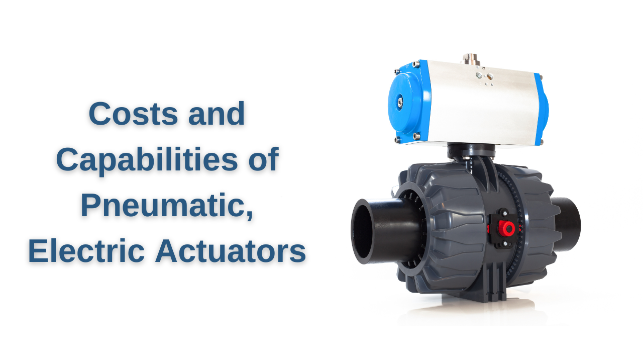
Pneumatic or electric? It’s not a new question. The merits of each have long been subject to discussion, but a fair amount of confusion continues to exist about which makes more sense for what. For example, are you considering replacing a compressor and 200 pneumatic cylinders with electric actuators because you think you’ll save on compressor costs? Or, perhaps you are thinking about building a new machine with pneumatics because 30 electric actuators are far too expensive. Make the wrong decision in either case and you could waste tens of thousands of dollars a year.
Pneumatic or electric? It’s not a new question. The merits of each have long been subject to discussion, but a fair amount of confusion continues to exist about which makes more sense for what. For example, are you considering replacing a compressor and 200 pneumatic cylinders with electric actuators because you think you’ll save on compressor costs? Or, perhaps you are thinking about building a new machine with pneumatics because 30 electric actuators are far too expensive. Make the wrong decision in either case and you could waste tens of thousands of dollars a year.
Whether the mismatch was due to the variation in required pump output or incorrect sizing of the pump, there is no question that the ability to easily vary pump speed has been a major advance in the overall performance of a pumping system. This has increased the energy efficiency, as well as the reliability of the equipment. Problems—such as cavitation or shaft deflection—can be alleviated by running the pump at optimal system speed. But how do variable speed drives affect mechanical seals?
Whether the mismatch was due to the variation in required pump output or incorrect sizing of the pump, there is no question that the ability to easily vary pump speed has been a major advance in the overall performance of a pumping system. This has increased the energy efficiency, as well as the reliability of the equipment. Problems—such as cavitation or shaft deflection—can be alleviated by running the pump at optimal system speed. But how do variable speed drives affect mechanical seals?