Solving Hydraulic System Overheating Problems
I was asked recently to investigate and solve an overheating problem in a mobile hydraulics application. The hydraulic system that was overheating comprised a diesel-hydraulic power unit, which was being used to power a pipe-cutting saw. The saw was designed for sub-sea use and was connected to the hydraulic power unit on the surface via a 710-foot umbilical. The operating requirements for the saw were 24 gpm at 3000 psi.
Why do hydraulic systems overheat?
Heating of hydraulic fluid in operation is caused by inefficiencies. Inefficiencies result in losses of input power, which are converted to heat. A hydraulic system’s heat load is equal to the total power lost (PL) through inefficiencies and can be expressed as:
PLtotal = PLpump + PLvalves + PLplumbing + PLactuators
If the total input power lost to heat is greater than the heat dissipated, the hydraulic system will eventually overheat.
Hydraulic fluid temperature – how hot is ‘too hot’?
Hydraulic fluid temperatures above 180°F (82°C) damage most seal compounds and accelerate degradation of the oil. While the operation of any hydraulic system at temperatures above 180°F should be avoided, fluid temperature is too high when viscosity falls below the optimum value for the hydraulic system’s components. This can occur well below 180°F, depending on the fluid’s viscosity grade.
Maintaining stable hydraulic fluid temperature
To achieve stable fluid temperature, a hydraulic system’s capacity to dissipate heat must exceed its inherent heat load. For example, a system with continuous input power of 100 kW and an efficiency of 80% needs to be capable of dissipating a heat load of at least 20 kW. It’s important to note that an increase in heat load or a reduction in a hydraulic system’s capacity to dissipate heat will alter the balance between heat load and dissipation.
Returning to the above example, the hydraulic power unit had a continuous power rating of 37 kW and was fitted with an air-blast heat exchanger. The exchanger was capable of dissipating 10 kW of heat under ambient conditions or 27% of available input power (10/37 x 100 = 27). This is adequate from a design perspective. The performance of all cooling circuit components were operating within design limits.
Pressure drop means heat
At this point it was clear that the overheating problem was being caused by excessive heat load. Concerned about the length of the umbilical, I calculated its pressure drop. The theoretical pressure drop across 710 feet of ¾” pressure hose at 24 gpm is 800 psi. The pressure drop across the same length of 1″ return hose is 200 psi. The formula for these calculations are available here. The theoretical heat load produced by the pressure drop across the umbilical of 1,000 psi (800 + 200 = 1000) was 10.35 kW. The formula for this calculation is available here.
This meant that the heat load of the umbilical was 0.35 kW more than the heat dissipation capacity of the hydraulic system’s heat exchanger. This, when combined with the system’s normal heat load (inefficiencies) was causing the hydraulic system to overheat.
Beat the heat
There are two ways to solve overheating problems in hydraulic systems:
- decrease heat load; or
- increase heat dissipation.
Decreasing heat load is always the preferred option because it increases the efficiency of the hydraulic system. In the above example, the heat load of the umbilical alone was nearly 30% of available input power, a figure that would normally be considered unacceptable. Decreasing this heat load to an acceptable level would have involved reducing the pressure drop, by replacing the pressure and return lines in the umbilical with larger diameter hoses. The cost of doing this for what was a temporary installation meant that, in this case, the most economical solution was to install additional cooling capacity in the circuit
Continuing to operate a hydraulic system when the fluid is over-temperature is similar to operating an internal combustion engine with high coolant temperature. Damage is guaranteed. Therefore, whenever a hydraulic system starts to overheat, shut it down, identify the cause and fix it.
Need help troubleshooting your hydraulic system?
Related Articles
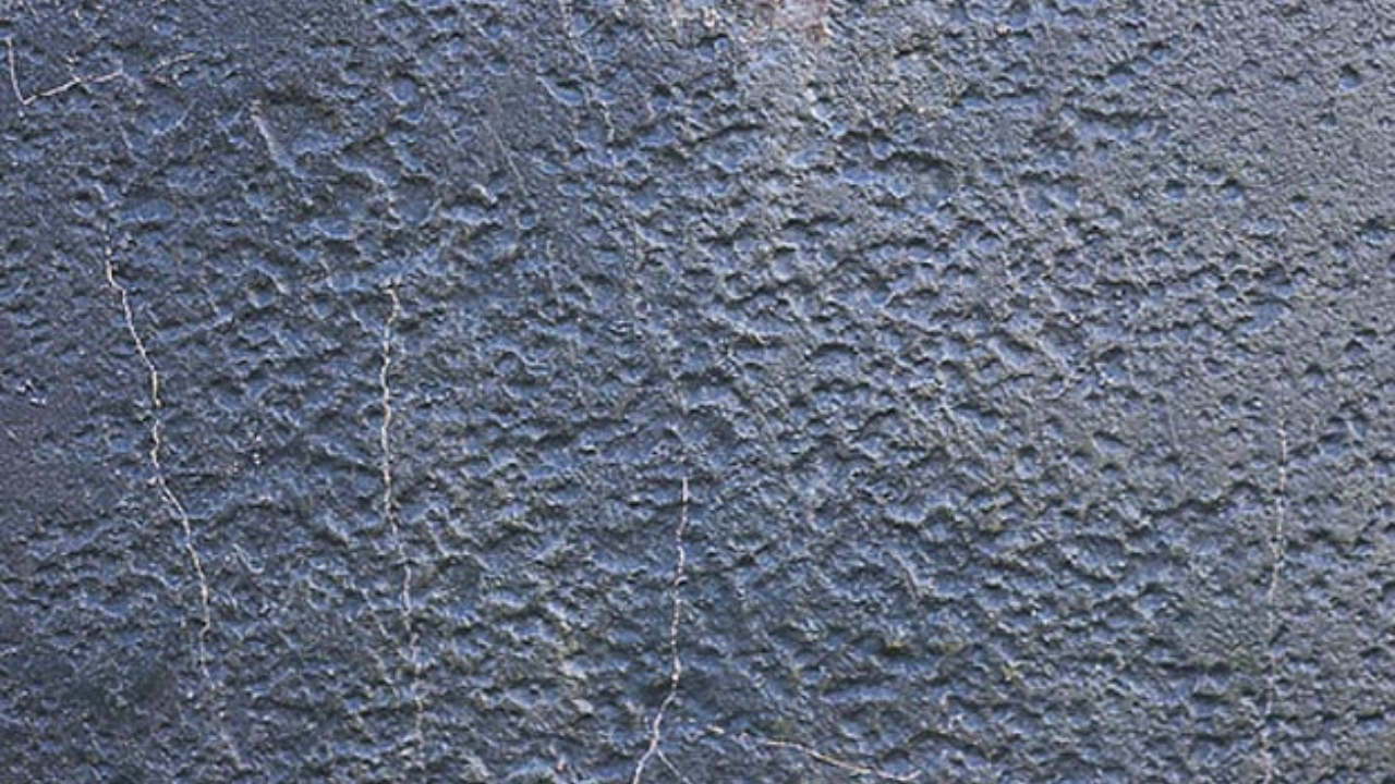
Pump cavitation is defined as the phenomenon of formation and consequent implosion of vapor bubbles in a region where the pressure of the liquid falls below its vapor pressure. Cavitation can occur in any fluid handling equipment, especially in pumps, one of the most important components of industry today. Technological advances in industrial protective coatings and repair composite materials have made it possible to repair pumps suffering from cavitation rather than simply replacing them.
Pump cavitation is defined as the phenomenon of formation and consequent implosion of vapor bubbles in a region where the pressure of the liquid falls below its vapor pressure. Cavitation can occur in any fluid handling equipment, especially in pumps, one of the most important components of industry today. Technological advances in industrial protective coatings and repair composite materials have made it possible to repair pumps suffering from cavitation rather than simply replacing them.
See More
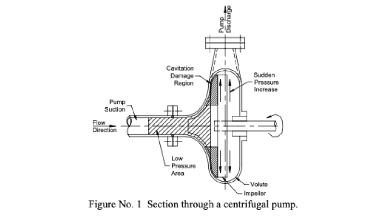
A standard centrifugal pump impeller is constructed of a group of elongated, solid-walled chambers attached together in the shape of a circular ring. The ring is spun quickly and the liquid that enters the inside end of the chambers is flung out at high speed from the other end. Figure No. 1 shows a section through centrifugal pump wet-end showing regions of low and high pressures.
A standard centrifugal pump impeller is constructed of a group of elongated, solid-walled chambers attached together in the shape of a circular ring. The ring is spun quickly and the liquid that enters the inside end of the chambers is flung out at high speed from the other end. Figure No. 1 shows a section through centrifugal pump wet-end showing regions of low and high pressures.
See More
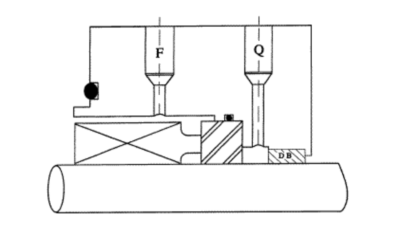
The seal gland is that part that holds the stationary half of the mechanical seal and attaches to the stuffing box. The most universally used gland is labeled the American Petroleum Institute (API) gland. The API (American Petroleum Institute) gland incorporates several important environmental controls and safety features. It should be specified for all petroleum refinery service because of the danger of an explosion or fire, but should also be recommended any time you are pumping any type of dangerous product. The gland has several features you need to understand.
The seal gland is that part that holds the stationary half of the mechanical seal and attaches to the stuffing box. The most universally used gland is labeled the American Petroleum Institute (API) gland. The API (American Petroleum Institute) gland incorporates several important environmental controls and safety features. It should be specified for all petroleum refinery service because of the danger of an explosion or fire, but should also be recommended any time you are pumping any type of dangerous product. The gland has several features you need to understand.
See More
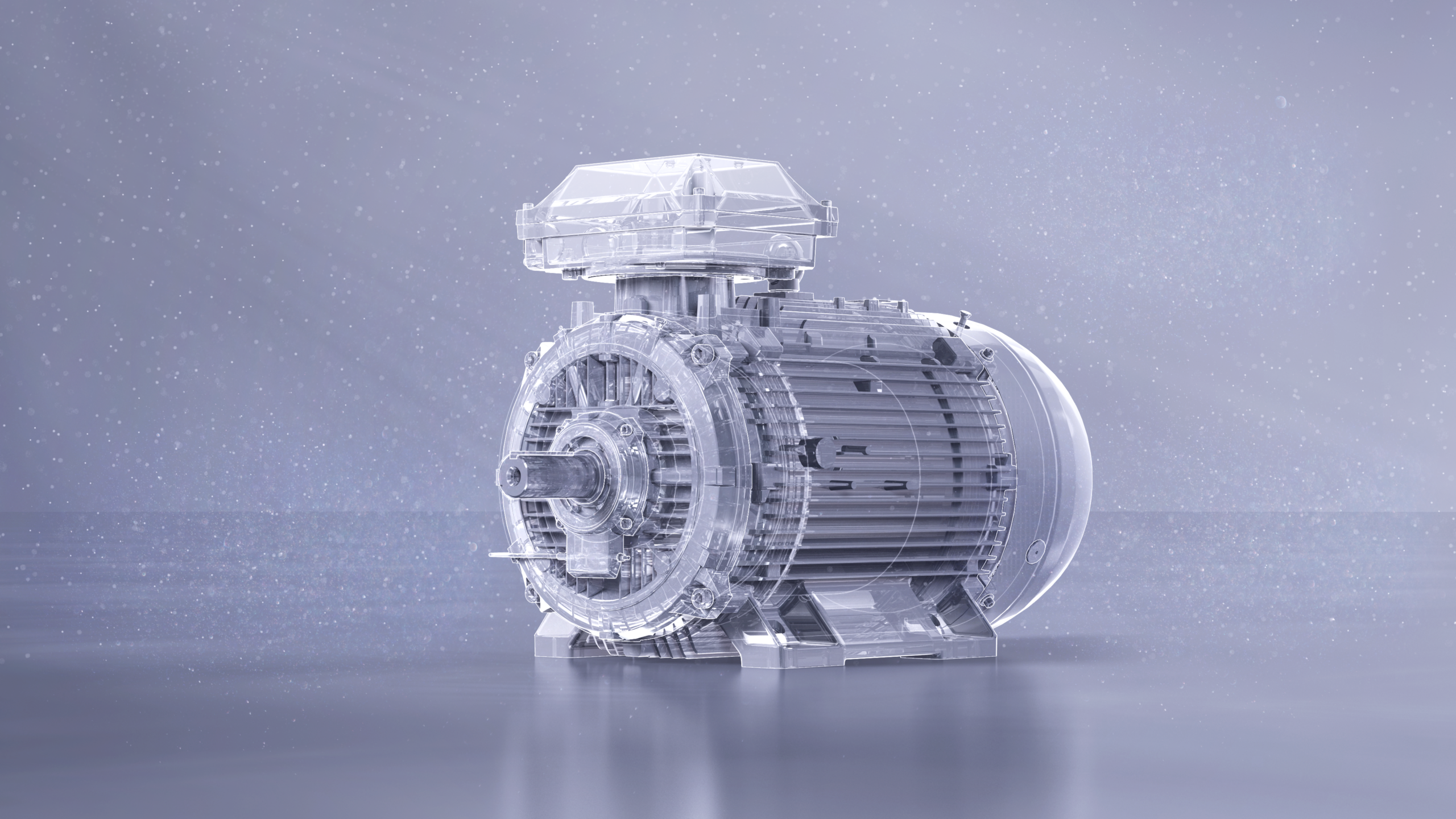
Safety is critical in this industry, especially for applications in potentially explosive environments. Introducing the new IE5 SynRM Increased Safety motors represents a game changer, giving chemical manufacturers access to the most energy-efficient motor and drive technology. The new motors offer up to 40 percent lower energy losses than commonly used IE3 motors while meeting stringent safety standards.
Safety is critical in this industry, especially for applications in potentially explosive environments. Introducing the new IE5 SynRM Increased Safety motors represents a game changer, giving chemical manufacturers access to the most energy-efficient motor and drive technology. The new motors offer up to 40 percent lower energy losses than commonly used IE3 motors while meeting stringent safety standards.
See More
How do fluids flow in pipes? This article explains what happens to fluids flowing through pipes. A fluid is either a liquid or a gas. In industry they are piped from storage to the point of use. Correct design and installation of the piping system minimizes pressure loss and improves the behavior of equipment and processes.
How do fluids flow in pipes? This article explains what happens to fluids flowing through pipes. A fluid is either a liquid or a gas. In industry they are piped from storage to the point of use. Correct design and installation of the piping system minimizes pressure loss and improves the behavior of equipment and processes.
See More
Stress in metals causes failure. Too much stress in metal will cause it to fail.
Stress in metals causes failure. Too much stress in metal will cause it to fail.
See More
Research into bearing failures1 shows that just over half of them are a result of contamination of the bearing oil. Clearly, it is essential to ensure that this is minimized and, if possible, eliminated to achieve the optimum bearing life necessary to improve equipment reliability.
Research into bearing failures1 shows that just over half of them are a result of contamination of the bearing oil. Clearly, it is essential to ensure that this is minimized and, if possible, eliminated to achieve the optimum bearing life necessary to improve equipment reliability.
See More