

Pump Maintenance Basics: Service Duty and Shaft Alignment
Mike Sondalini, PWW EAM System Consultant
with permission of BIN95 Business Industrial Network
Posted 7/23/2026
Changing the Service Duty of a Pump
When centrifugal pumps are modified to perform a different duty the new service head, flow and motor power characteristics are calculated from the Similarity Laws.
When there is a need to determine a new service duty for a centrifugal pump, and no performance curves are available, the recommended method is to use the Similarity Laws. These laws are derived by the use of dimensional analysis in which selected variables affecting performance are grouped in such a way that permit prediction of scaling effects when the variables are altered.
The laws are:

Where: Q is discharge flow in l/sec.
D is impeller diameter in mm.
ρ _is density in kg/m3.
N is impeller speed in rpm.
H is discharge head in meters.
Subscripts 1 and 2 represent initial and final conditions respectively. If in the equations above, the impeller diameter is held constant and the density is unchanged, the formulas reduce to the well-known Affinity Laws.

The users of these laws put a lot of faith in their ability to predict the required changes to a pump to achieve a new duty. Once the pump is altered it is costly to reverse the decision.
But how accurate are these formulas? To determine this, they are used to establish a new duty point for a centrifugal pump pumping water and the result compared to the published pump curves. The difference between the curves and the laws is then observable.
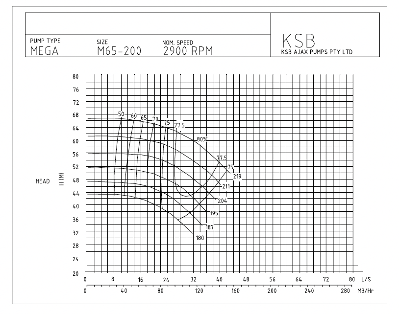
The calculations are for a common situation where a pump’s delivery head is to be reduced. In this case the impeller will require machining to a smaller diameter. The pump has an existing duty of 24 l/sec at 64m head with an impeller of diameter 219mm. If the impeller diameter is reduced to 195mm what is the new duty point calculated by the Similarity Laws? The applicable curves for the 219mm and 195mm impellers are shown on Figure 1.
Changing impeller size affects both the pump discharge head and the flow. This requires use of the Similarity Laws to calculate both the new head and the new flow.
The table below shows the start duty and the required duty using the Similarity Laws. The result is then compared to the published curve shown above for fixed speed service.

If instead the impeller diameter is reduced to 180 mm we get following results. If instead the impeller diameter is reduced to 180 mm we get following results.

From the results of the calculations it is clear that for this manufacturer’s pump the error in using the Similarity Laws is minor though it becomes larger the further the required duty point is from the existing duty point. These results provide some confidence in the use of the formulas. However, when the same method was used for other manufacturer’s pumps a discrepancy between the similarity laws and the pump curves of up to 7% was noted.
In situations where it is necessary to machine the impeller diameter down it is sensible to leave the impeller larger than calculated and reinstall it. Then establish the intermediate duty point and again calculate what impeller reduction is needed to attain the final required duty point.
For the alternate situation where a higher delivered head or flow is required, the Similarity Laws can be used to estimate the new faster impeller speed or to size a new larger impeller. When increasing the speed or the diameter of an impeller a higher head, flow and power draw result. The appropriate Similarity Law will provide a means to closely estimate the extent of the resulting change.


Shaft Alignment on Pumps
Shaft misalignment is one of the most common reasons for bearing and mechanical seal failures. Rotating misaligned shafts produce vibration and complex fluctuating radial and axial loads that lead to breakdowns. Shaft alignment is a precision maintenance requirement that requires exacting care and detail and if not performed will cause much production down time.
Misaligned shafts are the single greatest reason for failure of rotating equipment and connected components. When misaligned shafts are coupled together each shaft rotates about a different centre and has different orbits. If the two shaft positions in the orbits are not directly opposite each other the coupling is distorted. The coupling reacts to the distortion by pulling or pushing each shaft and which produces fluctuating forces throughout the equipment.
The axial, radial and bending forces developed by the ‘push-pull’ action, and the resulting non-circular shaft motion, is transferred through to bearings, shaft seals and, in pumps, to the mechanical seal. Vibration, fatigue and unnecessary damage result. The motion that causes the most damage is axial movement of the shaft. This is because parts are clamped together one against the other and there usually is little allowance for axial movement.
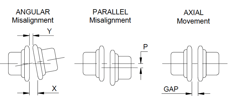
Figure 1 shows the types of misalignment.
In order to prevent rapid failure of equipment the shafts must be purposefully aligned to within very close tolerances. A simple way to look at it, for 4 pole motor speeds and slower, is that the centerlines of aligned shafts must be within 0.050 mm (0.002”) along their full length at operating temperature.
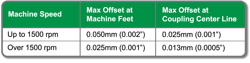
Table 1 shows alignment tolerances recommended by specialists after compiling equipment reliability data over many years and industries. Figure 2 shows an overhead view (plan view) of how Table 1 is applied.

This approach of aligning the whole machine guarantees parallel shafts and accurate coupling alignment. The common practice of measuring between and across the coupling faces can produce a coupling within alignment tolerance but with backends on both machines still skewed.
The Causes of Misalignment
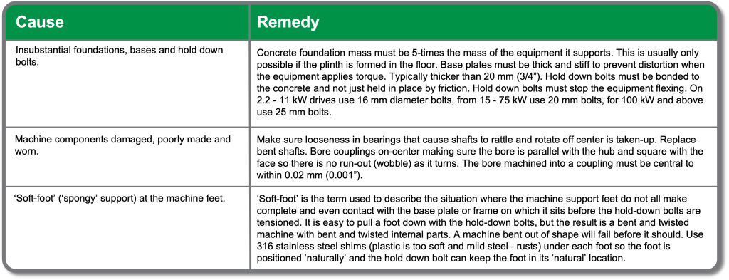
To prevent misalignment becoming a serious cause of equipment failure it is necessary to understand why it occurs so it can be corrected. Table 2 lists the most common causes of pump shaft misalignment and explains what to do in each case.

Related Articles


Back to Basics: Understanding Reliability Block Diagrams (RBD)
DC Motor Brush Holder and the Performance of Carbon Brushes

Chemical Corrosion Control