What are Angular Contact Bearings?
Mike Sondalini, PWW EAM System Consultant
with permission of BIN95 Business Industrial Network
Posted 4/28/2026
Angular contact bearings are used on shafts that encounter axial forces or combined loads (both axial and radial forces). Examples are centrifugal and helical rotor pump shafts and helical and worm gear shafts in gearboxes. Their design only permits axial forces in one direction. For alternating axial loads they must be installed as a bearing set to accommodate the forces from both directions. When set back to back, and less so when set face to face, they act to stiffen the shaft and handle larger bending moments such as overhung components or high midpoint shaft loading.

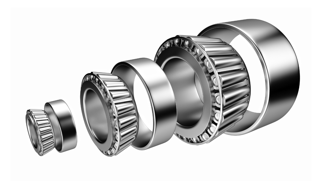
Figure 1 shows angular contact bearings in a back to back arrangement (left) and in an opposing arrangement.
When in direct contact (left of Figure 1) they are good bearings to use as locating bearings on a shaft because they can take combined loads. They are not suitable for the non-locating bearing because the ‘floating’ bearing must allow shaft axial movement due to thermal growth.
The shaft must always be allowed to expand along its length. This is achieved by installing a fixed bearing (the locating bearing) at one point and mounting the other bearings so they can move axially. Select bearings for the ‘floating’ positions that allow the inner raceway to slide past the rolling element (e.g. cylindrical roller bearings) or fix the bearing on the shaft but leave the outer race loose in the housing.
The biggest limitation of angular contact bearings is their inability to accommodate shaft misalignment. It is critical that parts be machined true to the axis, that tolerances and alignments be checked during installation and confirmed suitable, that components be made of materials and have cross-sections which resist bending. Misalignment causes forces that produce greater ball bearing loads and retaining cage stresses. The higher stresses reduce bearing life.
The correct internal clearance and preload in single row angular contact bearings can only be achieved after mounting them on the shaft and adjusting them against a second bearing providing axial location in the opposite direction (right of Figure 1). When used back-to-back or face-to-face the clearance cannot be adjusted. It must be provided by proper choice of bearings with appropriate clearances and use of fits for the shaft and the housing that on assembly gives the necessary clearance and preload.
Axial preload is used to prevent the balls sliding on the raceway. As the shaft rotates the rolling balls also move around the shaft but at a different speed. When the balls move into the loading zone, they must start to roll over the raceway and take their share of the load. If instead there is too much clearance between ball and raceway the ball can skid. This can cause the lubricant film between ball and raceway to separate and allow contact.
Axial preload makes the rolling elements and raceway come into contact on purpose so no clearance exists between them when they are still. There is very slight deformation of the raceway and the balls. The lubricant film builds-up between the race and the ball when they are moving.
Preload is also provided to counter thermal growth and insure that at operating temperature the correct clearances are kept in the bearing. Where the shaft growth is more than the bearing housing growth any preload will be increased by the differential expansion. In such cases it is necessary to leave clearance at assembly so that at running temperature the expansions achieve the correct clearances.
Set clearance and preload to that recommended by the manufacturer for the bearing size and running temperature. To maintain correct clearance when in operation, and to create a load zone, bearings set back-to-back or face-to-face must be subject to additional radial loads above that of the preload. This can be done by increasing the drive belt tension or by ensuring the self-weight of the shaft and components are more than the preload force.

Related Articles
Troubleshoot AC Motors

Pitfalls of Pump Piping

How Can I Extend the Performance Range of Standard Cartridge Mechanical Seals?

The Importance of Equipment Fit, Tolerance, and Clearance

Protecting Cooling Water Systems – Part 2
Basis for Bearing Life Calculation