Anatomy of a Boiler Failure – A Different Perspective
Gary J. Bases
The power industry’s operating and maintenance practices were held up to intense regulator and public scrutiny when on November 6, 2007, a Massachusetts power plant’s steam-generating boiler exploded and three men died. The Department of Public Safety’s Incident Report investigation (PDF) determined that the primary cause of the Dominion Energy New England’s Salem Harbor Generating Station Unit 3 explosion was extensive corrosion of boiler tubes in the division wall at the east furnace lower slope dead air space (Figure 1). The three operators were working directly below the furnace on a pulverizer seal air fan when the explosion occurred. They died of burns and related complications. The boiler was operating at 1,900 psi at the time of the failure. A complete set of photos of the boiler failure is included in the Incident Report.
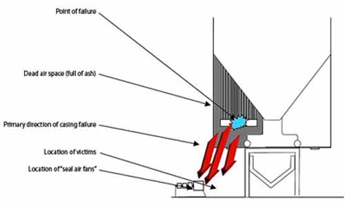
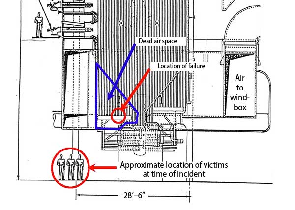
The report concluded that when the tubes failed within the dead air space formed by the division wall—an area normally under a slight negative pressure—the vestibule was instantly pressurized, causing a secondary rupture of the boiler casing around the bottom of the furnace. Ash and 600F steam was then released into the area where the three workers were located (Figure 2).
The report also summarized interviews with plant operations staff on standard plant operating and maintenance habits. Because the plant has operated as a cycling unit for the past 10 years or so, planned outages were so reduced in length that required maintenance activities were not completed. At the time of the accident, approximately 2,500 work orders were pending.
The report also noted that the dead air space had not been opened or inspected in at least 10 years and was full of ash at the time of the explosion. The report concluded that the tube explosion that blew out the outer wall of the furnace was caused by ash and water from boiler washing, coming into contact with tubes. That mixture caused corrosion that resulted in excessive tube metal loss.
The report held the chief engineer and the outside boiler inspector were directly responsible for the explosion because they failed to perform a comprehensive inspection as required by Massachusetts law. In other words, the catastrophe could have been prevented if proper inspections had been made of the entire furnace and more than visual inspection techniques had been used. The Occupational Safety and Health Administration since has found 10 serious safety violations at the plant, including failure to enter and inspect the area where the tube rupture occurred.
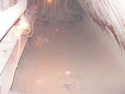
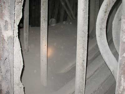
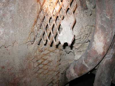
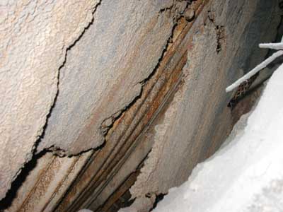
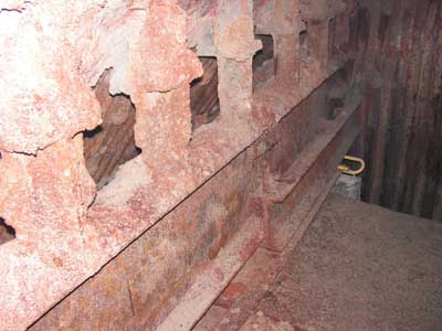
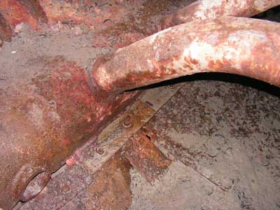
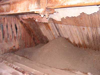
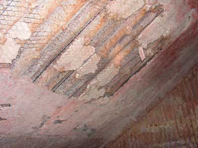
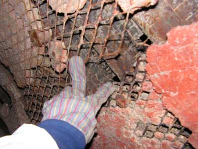
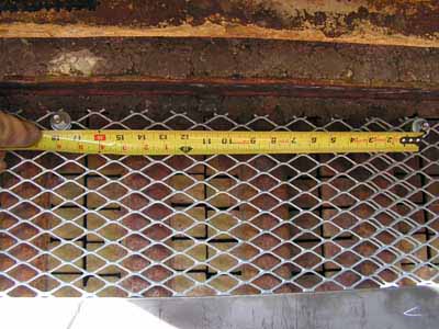
We must not close the book on this tragedy and chalk it up to bad luck on the part of this plant’s staff. There is much more to the story than what is written in the Incident Report. Here is the key question that the report failed to answer: What caused the vestibule to fill up with flyash in the first place (Figures 3 and 4)?
I believe that the root cause of the accident was refractory failure that allowed the water and ash to enter the vestibule in the first place. A properly installed and maintained refractory surface would have prevented the corrosion and, thus, the accident.
Good Boiler Design Practice
The report states that the boiler’s lower vestibule was full of flyash and had been for a very long time. Post-accident operator interviews suggest the flyash may be have been there as long as 10 years. Poor maintenance and inspection practices ignored this enclosed space. Not surprisingly, this lack of attention is common throughout the power industry.
The boiler is a 1957 vintage 120-MW coal-fired radiant power boiler. This was a common boiler design for virtually all utility boilers built from the mid-1940s through the 1960s. It was not until 1964 that the membrane tube wall design was developed and became the norm in utility boiler practice. During this time period approximately 400 boilers of this design were built in the U.S., and most are still in operation. All of these boilers had similar steam capacity, tube wall construction, vestibules, and refractory/tube wall design. Does the boiler cross-section in Figure 5 look familiar to you?
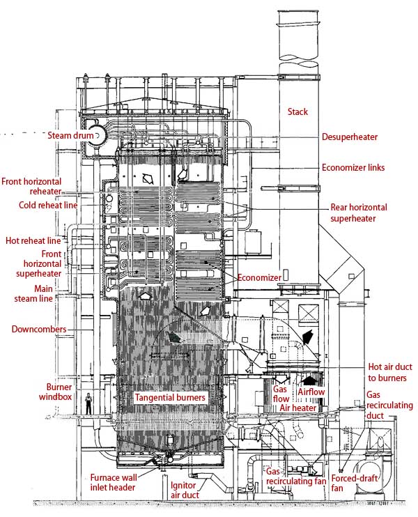
These are considered flat-studded or tangential-type boilers. They do not have membrane tube walls, but rather use either flat-studded tubes or bare loose tubes to form the boiler and furnace walls. To keep the fire (and fly ash) inside the firebox, refractory is applied over the outside of the tubes to form a protective, insulating wall.
Boilers of this type used either an “all-refractory design” with refractory (1 to 2 inches thick) on the back side of the tubes or an “inner-cased design,” which uses a thin layer of refractory applied flush with the back side of the tubes and a 10-gauge metal casing installed over the refractory-backed tubes. The all-refractory design was less costly, especially in areas such as vestibules and enclosures, and was therefore the most commonly used design. For this discussion, I focus on the “all-refractory design.”
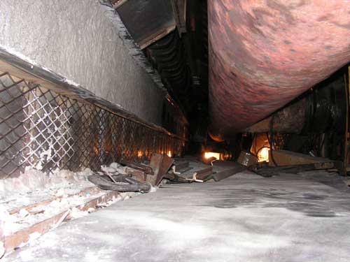
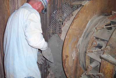
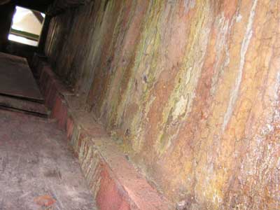
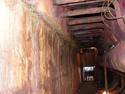
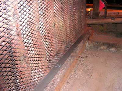
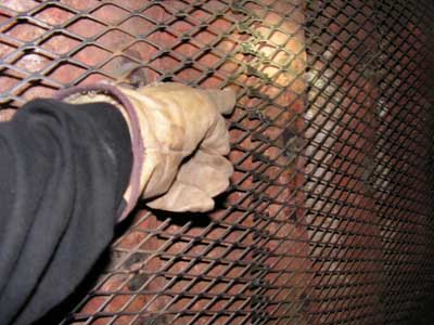
In essence, the refractory must keep the fire inside the box in order to keep the boiler operating efficiently and to prevent flyash from penetrating or entering the vestibules in and around the boiler (Figures 6 and 7). (Please note that the following photographs were not taken at Salem Harbor Unit 3 but at units of the same boiler design and configuration.)
These vestibules and enclosures are located under the superheater area, above the roof tubes, under drums, around the burner area, and below or just underneath the furnace hopper slope tubes where the failure occurred (Figures 8 and 9).
The boiler designers and manufactures of these types of boilers knew that it was very important to keep fly ash out of these vestibules because of the chemical constituents of fly ash. Fly ash is a by-product of burning coal and typically contains alkalis, such as sodium and potassium that can form corrosive mixtures in the presence of water, or sulfur, which can form sulfurous or sulfuric-type acids—both of which can corrode or weaken structural supports and tubes in the presence of water. Figures 10 through 14 illustrate these points in a boiler similar to Salem Harbor Unit 3’s in design and construction.
Poor Refractory Practices
Boilers of this vintage and design use refractory on the back side of tubes located inside vestibules and enclosures. The refractory is approximately 1 inch thick from the face of the tube and requires a support system. In my experience, the refractory can fail for any number of reasons, including these:
• Poor refractory mixing and handling practices.
• Poor installation practices (including curing and drying).
• Improper water-washing techniques.
• Improper refractory attachment systems.
The way to prevent failure is to mix, handle, and install refractory correctly and follow proper water-washing practices. Refractory mixing, handling, and installation errors can be eliminated by following the guidelines provided by any reputable refractory manufacturer and following common industry practices for installing the refractory. Refractory destruction by water washing can be avoided by not water washing in areas where vestibules and enclosures are located directly behind the waterwall tubes. If you must water wash, then do not spray directly into the refractory, which is located between the tubes.
Unfortunately, my experience has also been that many plants have an improper refractory attachment system that is by far the most common reason for a refractory failure inside vestibules and enclosures. A refractory attachment system will support the refractory, even during boiler expansion, regardless of how the refractory is installed. (The gunning installation method uses pressure to force dry material from the charging chamber through a hose to the point of placement; water is added at the discharge nozzle. The trowel method requires application of refractory by hand.)
Most plants pay little or no attention to the attachment system for holding refractory inside vestibule areas. The most common practices for holding expanded metal at power plants follow:
• No support system. The refractory will not last very long without a support system due the stresses associated with boiler expansion (Figure 15).
• A light-gauge attachment with clips. This application uses a thin-gauge attachment with insulation-type speed clips to support the expanded metal. This design is better for supporting ceramic module insulation applications than refractory. The thin gauge of the stud and clip does not last very long when exposed to stresses associated with boiler expansion (Figure 16).
• Welding directly to the tubes. This approach does not allow enough support of the refractory because most of the refractory material is located above the expanded metal. Due to stresses associated with boiler expansion, expanded metal should be placed in the middle of the refractory to give the optimum support (Figure 17).
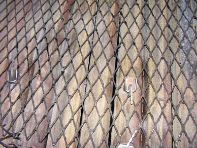
• The stud and clip method. This is a good method for holding expanded metal as long as a clip is placed both under and above the expanded metal. The clip should be a heavy-duty speed clip (such as SN3) and large enough to cover the diamond shape of the expanded metal openings. The problem with this system is the difficulty of keeping the expanded metal the same distance from the tube face. The distance of the expanded metal from the tube face is critical for the success and longevity of the system (Figure 18).
• A hex nut and threaded stud with washers. This system is a variation of the stud and clip except that it uses hex nuts and washers for holding the expanded metal instead of a speed clip. This is a good method for holding expanded metal as long as the washers are placed both under and above the expanded metal. The heavy-duty (12-gauge minimum) washers should be large enough to cover the diamond shape of the expanded metal openings. The problem with this system is the difficulty of keeping the expanded metal the same distance from the tube face. The distance of the expanded metal from the tube face is critical for the success and longevity of this system (Figures 19).
A properly supported refractory should last 10 years or more if the refractory is installed (and dried) correctly. All of the systems mentioned above have some drawbacks that could compromise the strength of the refractory support system and, consequently, affect refractory longevity.
Here is a method for holding 1-inch-thick refractory over the back side of tubes located inside a vestibule or enclosure that has the best chance for lasting 10 years or more:
1. Weld a ½-inch carbon steel hex nut face down (not on its edge) directly to the tube face on 12-inch horizontal x 18-inch vertical for flat areas and 12-inch x 12-inch centers on sloped or overhead areas. The ½-inch nut will act as a standoff, so the expanded metal will be located exactly in the middle of the refractory. 2.
2. Weld 1½-inch x 9-gauge (13-gauge minimum) non-flattened expanded metal directly to the hex nut. Using this size of expanded metal will allow both the fines and course aggregate grain to penetrate through the expanded metal. Using a smaller size of expanded metal will cause a separation betweens the fines and course grains in the refractory. That separation reduces the strength of the refractory and will affect its longevity.
3. The expanded metal should be overlapped by 1 inch to 3 inches in all directions. This overlapping helps locate the expanded metal so welding is possible at all hex nut locations and will take up the stresses associated with boiler expansion. The expanded metal is never welded in the overlap areas (Figure 20).6.
4. Apply a medium-weight 2,000F minimum, 45% alumina cement-bonded refractory 1 inch over the face of tubes through the expanded metal. It takes approximately an additional ½-inch thickness of refractory to completely cover the expanded metal. Remember that using more refractory than required does not give you a stronger or better refractory application.
5. Cure the installed refractory for 24 hours by spraying/wetting the surface of the refractory with water every two hours or by spraying/painting the surface of the refractory with water-based acrylic curing and sealing compound.
6. Dry the refractory during boiler start-up by raising the boiler temperature 75F per hour until the water/steam temperature inside the furnace wall tubes reaches between 250F and 400F and hold it there for two hours. This will drive out the mechanical water used in the mixing process from the refractory. Then take your boiler up at 75F per hour to operating temperature.
Look to the Future
The root cause of the tragedy in Massachusetts should have been identified as refractory failure rather than tube failure. It was the failed refractory lining that allowed flyash and water to penetrate into the lower furnace vestibule. The natural consequence of large ash deposits mixed with water and packed around boiler tubes was preventable.
The tragedy in Massachusetts would never have occurred if proper boiler inspection and maintenance practices had been followed. It is time for everyone working in or affiliated with the power industry to do their part to make sure this kind of accident will never happen again.
The industry can honor the memory of those lost by ensuring that a similar accident never occurs again by:
• Ensuring that boiler outages allow sufficient time for inspection and repair of refractory.
• Following proper procedures for handling and installing refractory.
• Paying very close attention to the refractory support system inside vestibules.
• Allowing enough time during boiler start-up procedures to dry the refractory.
• Avoiding water-washing tube walls in vestibule areas.
• Regularly inspecting vestibules and dead air spaces and quickly repairing damaged refractory.
Gary Bases is the President of BRIL Inc.
Related Articles

What is More Important - the Digital Tool or its Users
Chain Drive Design Recommendations

Getting Root Cause Analysis to Work for You
10 Steps to Pump Reliability - Part 2

Determining Accurate Alignment Targets

Pumps: You Get What You Pay For... Or Do You?