Stress in metals causes failure. Too much stress in metal will cause it to fail. Failure can occur by putting the metal under a once-only load greater than it can take or by metal fatigue from continually loading the metal cyclically with a high load less than the breaking load. Stress produces strain at the molecular level in the metal and discontinuities between atoms come together to form microscopic cracks. Under continued stress the cracks grow and eventually the metal parts.
Stress occurs when forces pull (tension), push (compression) or act in combination on a material. When a force is applied the material reacts by distorting to counterbalance the force. A greater force will cause a correspondingly greater distortion until the item breaks.
Stress is the force applied per unit of cross-sectional area square to the force. The formula:
Stress (σ) = Force / unit of area
Metric system units are Newton per square meter (N/m2) and imperial system units are pounds per square inch (psi).
Strain is the amount the material deforms from the unloaded state when the force is applied. The formula:
Strain (ξ) = Change in length / original length
Strain has no units, as it is a ratio of length divided by a length. It represents a proportional change in size.
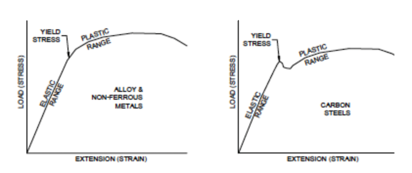
When a force is applied to a metal deformation occurs and it is strained. The more the force – the more the deformation (strain). This relationship is recognized in Hooke’s Law and is shown in Figure 1 for two types of metals.
Figure 1: Graphs of Hooke’s Law
Figure 1 indicates that metals have an elastic region where load and strain are proportional (a straight line on a graph). In this region the metal acts like a spring and when the load is removed the deformation (strain) reduces and it returns to its original shape. If instead the load increases, the strain (deformation) rises until a point is reached where the metal can no longer sustain the load and it yields. The yielding can be gradual as in the left-hand plot of Figure 1 or it can be sudden as in the right-hand plot.
The aim of much of the work in metallurgy is to discover how to extend the yield point further because in doing so we can fabricate items using thinner metals for less cost.
AT THE MOLECULAR LEVEL
The behavior of metals under load is a result of their atomic arrangement. When a material is loaded it deforms minutely in reaction to the load. The atoms in the material move closer together in compression and further apart in tension.
Consider the atomic bonds as being springs separating the atoms as shown in Figure 2. The springs are squeezed together in compression and pulled when in tension. The amount an atom moves from its neighbor is its strain. As a force is applied the atoms change a proportionate distance.
Figure 2: Atomic movement under applied strain.
This model however, does not explain why there is sudden yielding. With most modern metals yielding usually occurs at about 1% of the theoretic strength of the atomic bonds. Many materials yield at about 0.1% of the theoretic strength.
The reason metals have such low strengths is because of imperfect atomic structures in the crystal lattices which make them up. Often a row of atoms will stop mid crystal and a gap is created in the atomic structure. These gaps act as huge stress raising points known as dislocations.
EFFECT OF APPLYING LOADS ON A MATERIAL
A load applied to a metal is distributed along the atomic rows in the crystals. At the end of the rows forming dislocations the force is transferred to the bonds with neighboring atoms. Fewer bonds now carry greater loads and eventually fail as the force increases. As each atomic bond is broken and then remade with the next atom the dislocation moves an atom. Eventually the dislocation makes its way to the outside of the crystal. If sufficient dislocations accumulate at the crystal boundary the crystal separates from its neighbor.
Figure 3: Movement of a dislocation (the imaginary “wedge”)
It is the presence of dislocations in metal that allow deformation at low levels of stress. Eventually so many dislocations accumulate that insufficient atoms are left to take the load and the metal yields. Figure 3 indicates how the dislocation moves through the crystal.
REDUCING STRESSES
It is fortunate dislocations are present in metals for they allow us to form and shape metals using less energy than if they did not exist. Their presence requires us to be aware of how to prevent them from accumulating at grain boundaries so that they will not eventually lead to the failure of the item.
Table 1 shows some of the common methods used to reduce the influence of dislocations.
Grease – use the right one for the job. The classification, selection, and application of greases is included in this article. Greases are designed for specific applications and if used in the wrong service they will not be effective. Compare the properties of greases and check those used in your equipment are suited to the service.
Grease – use the right one for the job. The classification, selection, and application of greases is included in this article. Greases are designed for specific applications and if used in the wrong service they will not be effective. Compare the properties of greases and check those used in your equipment are suited to the service.
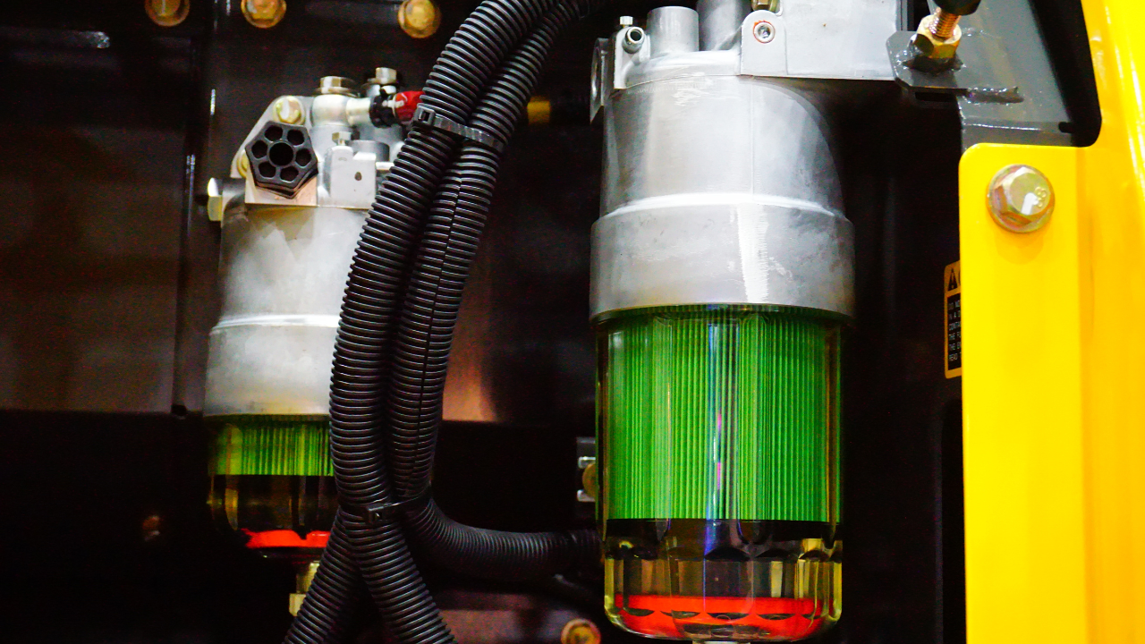
Given that particle contamination of hydraulic fluid reduces the service life of hydraulic components, it would seem logical that a system can never have too many hydraulic filters. Well... not exactly. Some hydraulic filters can actually do more harm than good and therefore their inclusion in a hydraulic system is sometimes misguided.
Given that particle contamination of hydraulic fluid reduces the service life of hydraulic components, it would seem logical that a system can never have too many hydraulic filters. Well... not exactly. Some hydraulic filters can actually do more harm than good and therefore their inclusion in a hydraulic system is sometimes misguided.
"What's the system's normal operating temperature? What's the system's usual operating pressure range?" If you can't answer these two basic questions about the vital signs of your hydraulic equipment I strongly recommend you make the effort to get to know your hydraulic equipment better. The information is easy to collect and can give valuable insight to the health of your hydraulic equipment.
"What's the system's normal operating temperature? What's the system's usual operating pressure range?" If you can't answer these two basic questions about the vital signs of your hydraulic equipment I strongly recommend you make the effort to get to know your hydraulic equipment better. The information is easy to collect and can give valuable insight to the health of your hydraulic equipment.
I was asked recently to investigate and solve an overheating problem in a mobile hydraulics application. The hydraulic system that was overheating comprised a diesel-hydraulic power unit, which was being used to power a pipe-cutting saw. The saw was designed for sub-sea use and was connected to the hydraulic power unit on the surface via a 710-foot umbilical. The operating requirements for the saw were 24 gpm at 3000 psi. Heating of hydraulic fluid in operation is caused by inefficiencies. Inefficiencies result in losses of input power, which are converted to heat. A hydraulic system's heat load is equal to the total power lost (PL) through inefficiencies.
I was asked recently to investigate and solve an overheating problem in a mobile hydraulics application. The hydraulic system that was overheating comprised a diesel-hydraulic power unit, which was being used to power a pipe-cutting saw. The saw was designed for sub-sea use and was connected to the hydraulic power unit on the surface via a 710-foot umbilical. The operating requirements for the saw were 24 gpm at 3000 psi. Heating of hydraulic fluid in operation is caused by inefficiencies. Inefficiencies result in losses of input power, which are converted to heat. A hydraulic system's heat load is equal to the total power lost (PL) through inefficiencies.
The previous article in this series, "Understanding Shaft Alignment: Thermal Growth," explained thermal growth and its affect on proper equipment alignment. A practical example involves a recent project at a wastewater treatment plant in Cleveland that needed realistic cold alignment targets for a 3600 rpm compressor to reach their accurate alignment targets.
The previous article in this series, "Understanding Shaft Alignment: Thermal Growth," explained thermal growth and its affect on proper equipment alignment. A practical example involves a recent project at a wastewater treatment plant in Cleveland that needed realistic cold alignment targets for a 3600 rpm compressor to reach their accurate alignment targets.
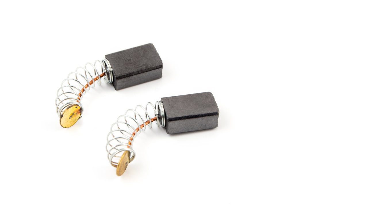
A motor brush is not a brush at all in the traditional sense. It is actually a carbon or graphite cube, commonly held in place by a spring, that acts as a conductor between the electrified stationary and rotating parts of a motor. The whole brush assembly is made up of a carbon block, one or more shunts, a spring and a holder. The carbon blocks are easily replaceable and are therefore intended as a wear part to prevent damage to more costly motor components.
A motor brush is not a brush at all in the traditional sense. It is actually a carbon or graphite cube, commonly held in place by a spring, that acts as a conductor between the electrified stationary and rotating parts of a motor. The whole brush assembly is made up of a carbon block, one or more shunts, a spring and a holder. The carbon blocks are easily replaceable and are therefore intended as a wear part to prevent damage to more costly motor components.
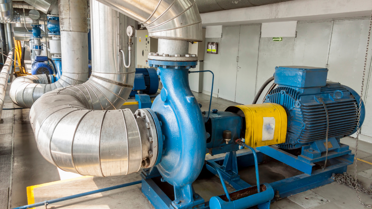
You may get the impression that implementing these steps will be costly and very difficult to achieve. The thing you need to bear in mind is: “You are already spending the money.” The only question is: “Are you getting the result from your pumping systems that you are looking for?” If you can create an environment that allows your entire team to become engaged in implementing these concepts, it will be the best investment you ever made.
You may get the impression that implementing these steps will be costly and very difficult to achieve. The thing you need to bear in mind is: “You are already spending the money.” The only question is: “Are you getting the result from your pumping systems that you are looking for?” If you can create an environment that allows your entire team to become engaged in implementing these concepts, it will be the best investment you ever made.