[webinar] Embracing Digital Transformation in Maintenance & Plant Operations | March 13 at 10AM EST – Register Now
Suction Bell Upgrades for Vertical Turbine Pumps
Suction Bell Upgrades for Vertical Turbine Pumps
Dr. Lev Nelik, P.E., APICS
How long should a vertical pump’s suction bell last? That was a question a plant manager asked me during a recent consulting assignment for a power plant. A pump manufacturer’s typical response to such a question is, “it depends.”
Basically, it depends upon the liquid being pumped, the operating point on a curve, the accumulated hours, the materials of construction, and so on. But is there an average value, or does a pump life vary within a very broad range? Is 30 years of life considered a very long time? Is two years unacceptably low?
If a large vertical cooling water or recirculating pump supplies water to the plant, 15 (or more) years of life should be achievable. Anything under five years is too short for most applications. If water comes in from the ocean or a gulf, the pump life (i.e. impeller, casing cone, suction bell) will be reduced, especially if a pump operates off-design, where suction recirculation is particularly damaging and the seawater is known to be very corrosive.
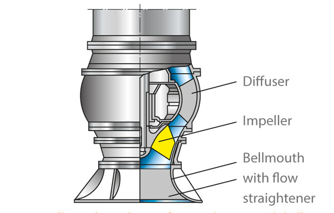
Often, damage to the impeller casing (cone — at immediate proximity to the vanes) is much more severe as compared to the damage of the suction bell (below the impeller) itself. In recognition of this fact, some designs are deliberately configured into a two-piece construction where the impeller casing (cone) is bolted to the suction bell, thus making it simpler to replace. For large vertical turbine pumps, these parts are expensive, and separating a shorter-expectancy-life part from a longer-expectancy-life part is a good idea.
Unfortunately, many designs configure the impeller casing and suction bell into one continuous unit because it is obviously cheaper to produce a single-piece casting. The problem here is that when the casing gets damaged, the entire part must be scrapped and replaced — and the end user pays for that.
When examining such a worn-out casing cone/ suction bell part, an effective upgrade strategy involves modifying the design by separating the part into two pieces and then bolting them back together. An example of such an upgrade was recently done by our repair shop.
Suction bells are usually constructed from iron, which is significantly less expensive than stainless steel but lacks its resistive properties. Upgrading an entire piece is another possibility, but it is often too expensive and really unnecessary. Instead, a two-piece construction will have a new stainless cone, bolted to the old bell and fitted with a stainless flange.
The result is a much better design, with stainless steel providing many more years of operation at enhanced resistance to corrosion and cavitation damage.
And should the lower portion (suction bell) eventually need repair, it can be done, saving time and money by reusing the undamaged stainless upper part.
We cannot change the single-piece past. But we can certainly improve the life of individual components, once the deficiencies of past practices are realized, understood — and corrected.
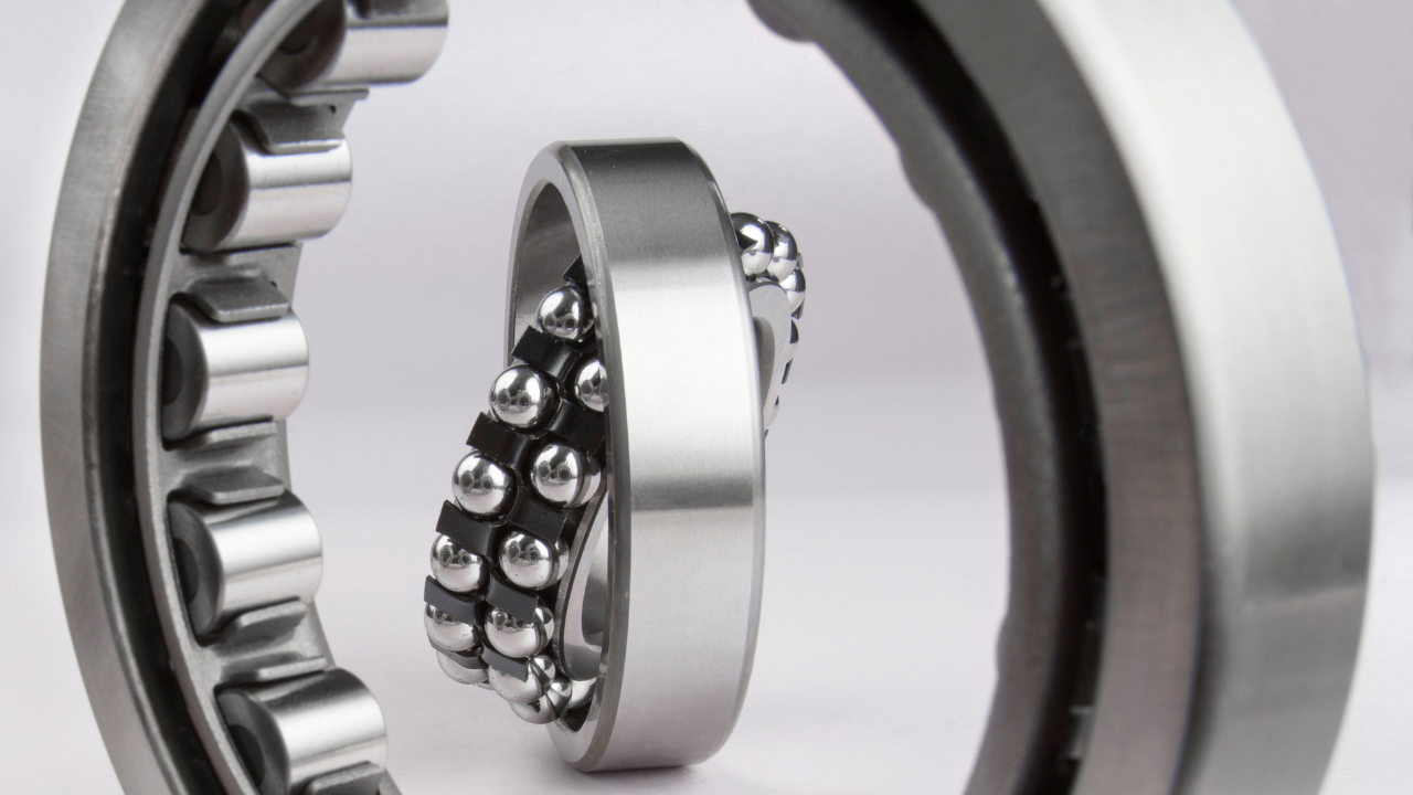
Experience shows seemingly identical rolling bearings operated under identical conditions may not last the same amount of time. In most cases, it is impractical to test a statistically significant number of bearings, so engineers rely on standardized bearing-life calculations to select and size bearings for a particular application. These calculations continue to evolve and become more accurate over time, reflecting the collective experience of the bearing industry, including recent advances in manufacturing, tribology, materials, end-user condition monitoring, and computation.
Experience shows seemingly identical rolling bearings operated under identical conditions may not last the same amount of time. In most cases, it is impractical to test a statistically significant number of bearings, so engineers rely on standardized bearing-life calculations to select and size bearings for a particular application. These calculations continue to evolve and become more accurate over time, reflecting the collective experience of the bearing industry, including recent advances in manufacturing, tribology, materials, end-user condition monitoring, and computation.
It turned out that the photoelectric sensor could only be adjusted to stay on all the time or off all the time when the cans were going by at any higher rate than Jog speed on the Seamer. We adjusted and adjusted the sensors. The sensors were replaced with new sensors. It did no good. The lines were stopped while we traced all the control and power wiring so we could try to determine if there was a problem in the wiring.
It turned out that the photoelectric sensor could only be adjusted to stay on all the time or off all the time when the cans were going by at any higher rate than Jog speed on the Seamer. We adjusted and adjusted the sensors. The sensors were replaced with new sensors. It did no good. The lines were stopped while we traced all the control and power wiring so we could try to determine if there was a problem in the wiring.
Selecting the right pump can pose a significant challenge due to the extensive array of options available for different applications. Each type of pump comes with distinct advantages and disadvantages that necessitate careful evaluation. In this article, we provide a comprehensive overview of prevalent pumping technologies and delve into the limitations associated with pump selection per applications.
Selecting the right pump can pose a significant challenge due to the extensive array of options available for different applications. Each type of pump comes with distinct advantages and disadvantages that necessitate careful evaluation. In this article, we provide a comprehensive overview of prevalent pumping technologies and delve into the limitations associated with pump selection per applications.
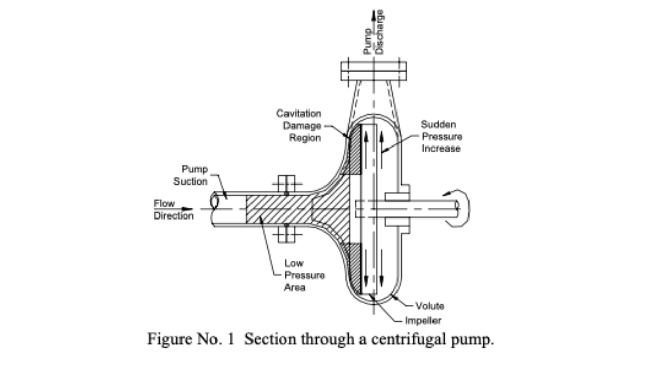
A standard centrifugal pump impeller is constructed of a group of elongated, solid-walled chambers attached together in the shape of a circular ring. The ring is spun quickly and the liquid that enters the inside end of the chambers is flung out at high speed from the other end. Figure No. 1 shows a section through centrifugal pump wet-end showing regions of low and high pressures.
A standard centrifugal pump impeller is constructed of a group of elongated, solid-walled chambers attached together in the shape of a circular ring. The ring is spun quickly and the liquid that enters the inside end of the chambers is flung out at high speed from the other end. Figure No. 1 shows a section through centrifugal pump wet-end showing regions of low and high pressures.
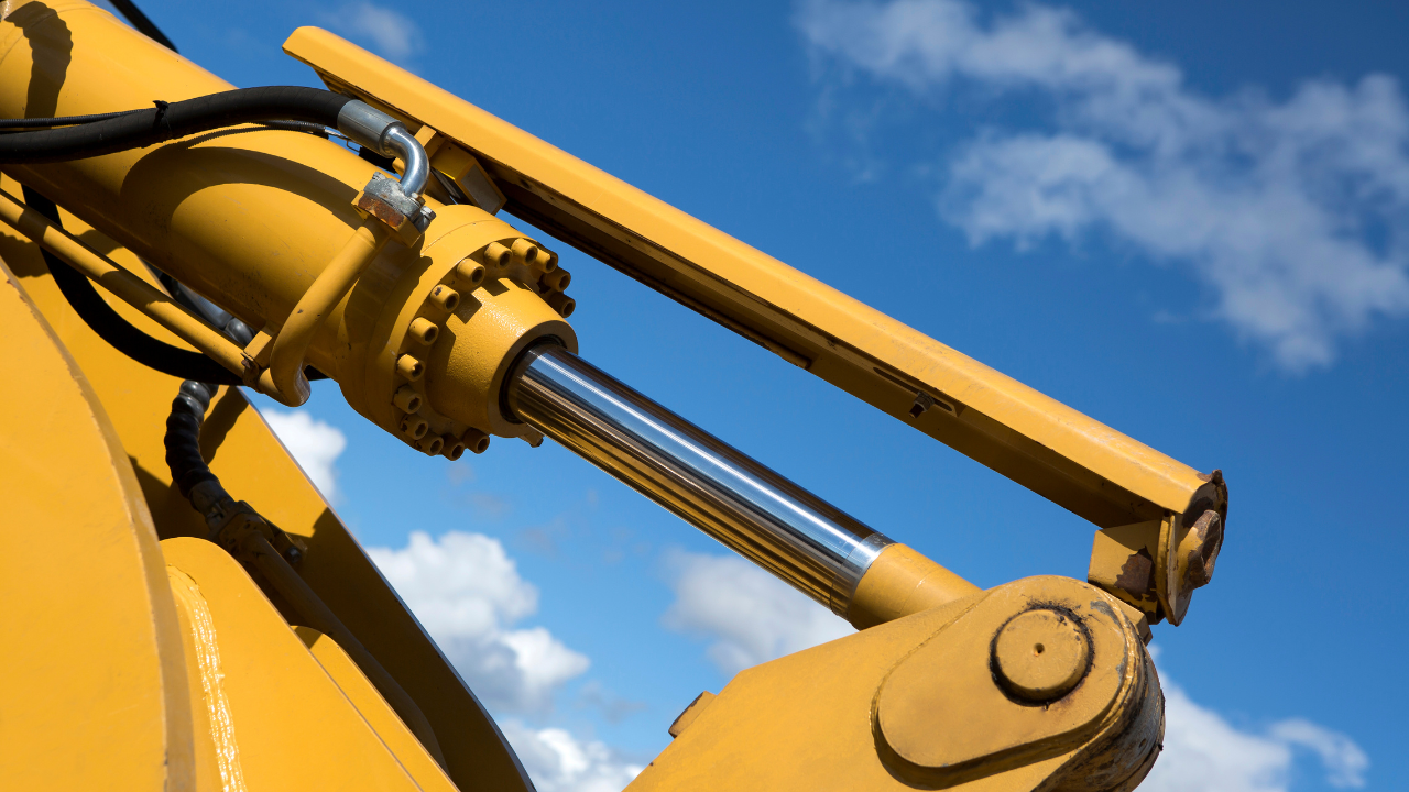
I was recently engaged by a client to conduct failure analysis on a large (and expensive) double-acting cylinder off a hydraulic excavator. This cylinder had been changed-out due to leaking rod seals after achieving only half of its expected service life. Inspection revealed that apart from the rod seals, which had failed as a result of the 'diesel effect', the other parts of the cylinder were in serviceable condition. The diesel effect occurs in a hydraulic cylinder when air is drawn past the rod seals, mixes with the hydraulic fluid and explodes when pressurized.
I was recently engaged by a client to conduct failure analysis on a large (and expensive) double-acting cylinder off a hydraulic excavator. This cylinder had been changed-out due to leaking rod seals after achieving only half of its expected service life. Inspection revealed that apart from the rod seals, which had failed as a result of the 'diesel effect', the other parts of the cylinder were in serviceable condition. The diesel effect occurs in a hydraulic cylinder when air is drawn past the rod seals, mixes with the hydraulic fluid and explodes when pressurized.
Several tests can be performed on a hydraulic pump to indicate its condition. The temperature of the pump case, the flow of the case drain and the current draw of the drive motor are common checks that can be done regularly and over a period of time to track the wear of a hydraulic pump.
Several tests can be performed on a hydraulic pump to indicate its condition. The temperature of the pump case, the flow of the case drain and the current draw of the drive motor are common checks that can be done regularly and over a period of time to track the wear of a hydraulic pump.
The majority of the failure mechanisms that significantly reduce the reliability and life of a centrifugal pump are caused by operation away from the pump best efficiency point (BEP). To achieve best-in-class life, it is essential to either operate close to the pump BEP (which is always the preferred method) or to provide provisions that anticipate the various effects of off-BEP operation and attempt to mitigate these consequences.
The majority of the failure mechanisms that significantly reduce the reliability and life of a centrifugal pump are caused by operation away from the pump best efficiency point (BEP). To achieve best-in-class life, it is essential to either operate close to the pump BEP (which is always the preferred method) or to provide provisions that anticipate the various effects of off-BEP operation and attempt to mitigate these consequences.