Basis for Bearing Life Calculation
The Timken Company
Bearing Life
Bearing life is defined as the length of time, or the number of revolutions, until a fatigue spall of a specific size develops. This spall size, regardless of the size of the bearing, is defined by an area of 0.01 inch2 (6 mm2). This life depends on many different factors such as loading, speed, lubrication, fitting, setting, operating temperature, contamination, maintenance, plus many other environmental factors. Due to all these factors, the life of an individual bearing is impossible to predict precisely. Also, bearings that may appear to be identical can exhibit considerable life scatter when tested under identical conditions. Remember also that statistically the life of multiple rows will always be less than the life of any given row in the system. For bearings where it is impossible to test a large number of bearings, the long experience of The Timken Company will help you in your L10 bearing life calculation.
L10 Bearing Life
L10 bearing life is the life that 90 percent of a group of apparently identical bearings will complete or exceed before the area of spalling reaches the defined 0.01 inch2 (6 mm2) size criterion. If handled, mounted, maintained, lubricated and used in the right way, the life of your tapered roller bearing will normally reach and even exceed the calculated L10 bearing life.
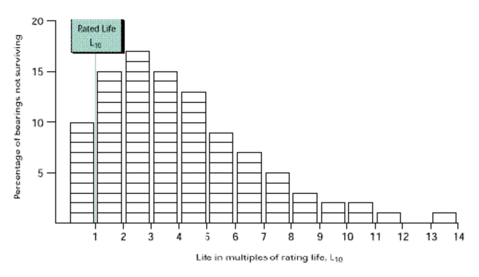
If a sample of apparently identical bearings is run under specific laboratory conditions, 90 percent of these bearings can be expected to exhibit lives greater than the rated life. Then, only 10 percent of the bearings tested would have lives less than this rated life. Figure 3-48 shows L10 bearing life scatter following a Weibull distribution function with a dispersion parameter equal to 1.5.
Bearing Life Equation
As you will see it in the following, there is more than just one bearing life calculation method, but in all cases the bearing life equation is :
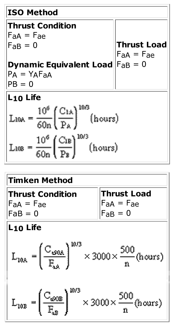
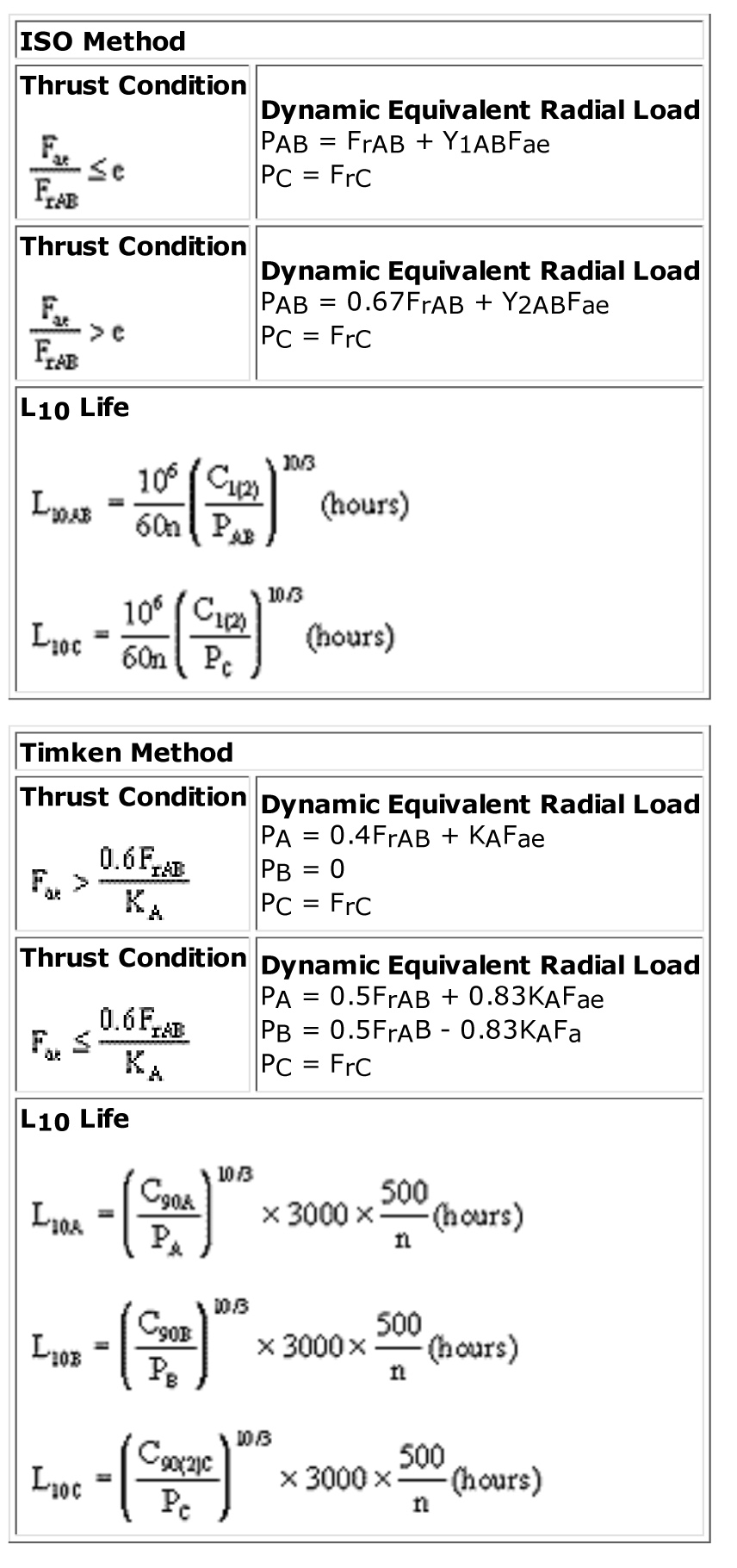
L10 = (C / P)10/3 × (B / n) × a
L10 in hours
C = radial rating of the bearing in lbf or N
P = radial load or dynamic equivalent radial load applied on the bearing in lbf or N. The calculation of P depends on the method (ISO or Timken) with combined axial and radial loading
B = factor dependent on the method ; B = 1.5 × 10⁶ for the Timken method (3000 hours at 500 rev/min) and 106/60 for the ISO method
a = life adjustment factor ; a = 1, when environmental conditions are not considered; n = rotational speed in rev/min.
This can be illustrated as follows :
- Doubling load reduces life to one tenth. Reducing load by one half increases life by ten,
- Doubling speed reduces life by one half. Reducing speed by one half doubles life.
In fact, the different life calculation methods applied (ISO 281, Timken method…) differ by the selection of the parameters used (i.e. the Timken formula is based on 90 million revolutions, whereas the others are based on 1 million revolutions).
Bearing Ratings
Depending on the life calculation method used, the bearing ratings have to be selected accordingly. The “Cr” rating, based on one million revolutions, is used for the ISO method, and the “C90” rating, based on 90 million revolutions, is utilized for the Timken method.
The Timken rating is also published based on 1 million revolutions : C1 = C90 × 3.857
This will enable you to make a direct comparison between Timken bearings and those using ratings evaluated on a basis of 1 million revolutions. However, a direct comparison between ratings of various manufacturers can be misleading due to differences in rating philosophy, material, manufacturing and design. In order to make a true geometrical comparison between the ratings of different bearing suppliers, only the rating defined following the ISO 281 equation should be used. However, by doing this, you do not take into account the different steel qualities from one supplier to another.
ISO 281 Dynamic Radial Load Rating Cr
This bearing rating equation is published by the International Organization for Standardization (ISO) and AFBMA. These ratings are not published by The Timken Company nor by any other bearing manufacturers. However, they can be obtained by contacting our company.
The basic dynamic load rating is function of:
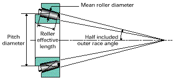
Cr = bm × fc × (i × Lwe × cos a)7/9 × Z3/4 × Dwe29/27
Cr = radial rating
bm = material constant (ISO 281 latest issue specifies a factor of 1.1)
fc = geometry dependent factor
i = number of bearing rows within the assembly
Lwe = effective roller contact length
a = bearing half-included outer race angle
Z = number of rollers per bearing row
Dwe = mean roller diameter
Timken Dynamic Radial Load Rating C90
Even though the ISO method allows you to compare different bearing suppliers, the basic philosophy of The Timken Company is to provide you with the most practical bearing rating for your bearing selection process. Since 1915 The Timken Company has developed and validated a specific rating method for its tapered roller bearings. The published Timken C90 ratings are based on a basic rated life of 90 million revolutions or 3000 hours at 500 rev/min.
To assure consistent quality worldwide, we conduct extensive bearing life fatigue tests in our laboratories. These audit tests result in a high level of confidence in our ratings. The basic dynamic load rating is used to estimate the life of a rotating bearing and is a function of:
| C90 = M × H × (i x Leff × cos a)4/5 × Z7/10 × Dwe16/15 | |
| C90 = radial rating | |
| M = material constant | |
| H = geometry dependent factor | |
| i = number of bearing rows within the assembly | |
| Leff = effective roller contact length | |
| a = bearing half-included outer race angle | |
| Z = number of rollers per bearing row | |
| Dwe = mean roller diameter |
A rating based on 90 million revolutions is more realistic as most applications equal or exceed this duration. For double row bearings in which both rows are loaded equally, the two-row rating considers the system life of the assembly as follows:
C90(2) = 24/5 × C90 or C90(2) = 1.74 × C90
The basic radial load rating of a four-row assembly is taken as two times the double row rating :
C90(4) = 2 × C90(2)
and for a six-row assembly as three times the double row rating :
C90(6) = 3 × C90(2)
The Timken Company also publishes K factors for its bearings. This factor is the ratio of basic dynamic radial load rating to basic dynamic thrust load rating of a single row bearing:

The Timken Company also publishes K factors for its bearings. This factor is the ratio of basic dynamic radial load rating to basic dynamic thrust load rating of a single row bearing:
| K = C90 / Ca90 | 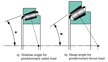 |
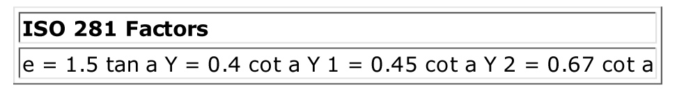
| The smaller the K factor, the steeper the bearing cup angle (fig. 3-51). The relationship can also be geometrically expressed as: | |
| K = 0.389 x cot a a = half included outer race angle |
L10 Bearing Life calculation
 |
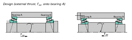
Single Row Bearing
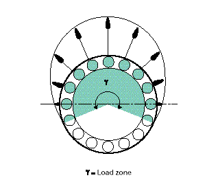
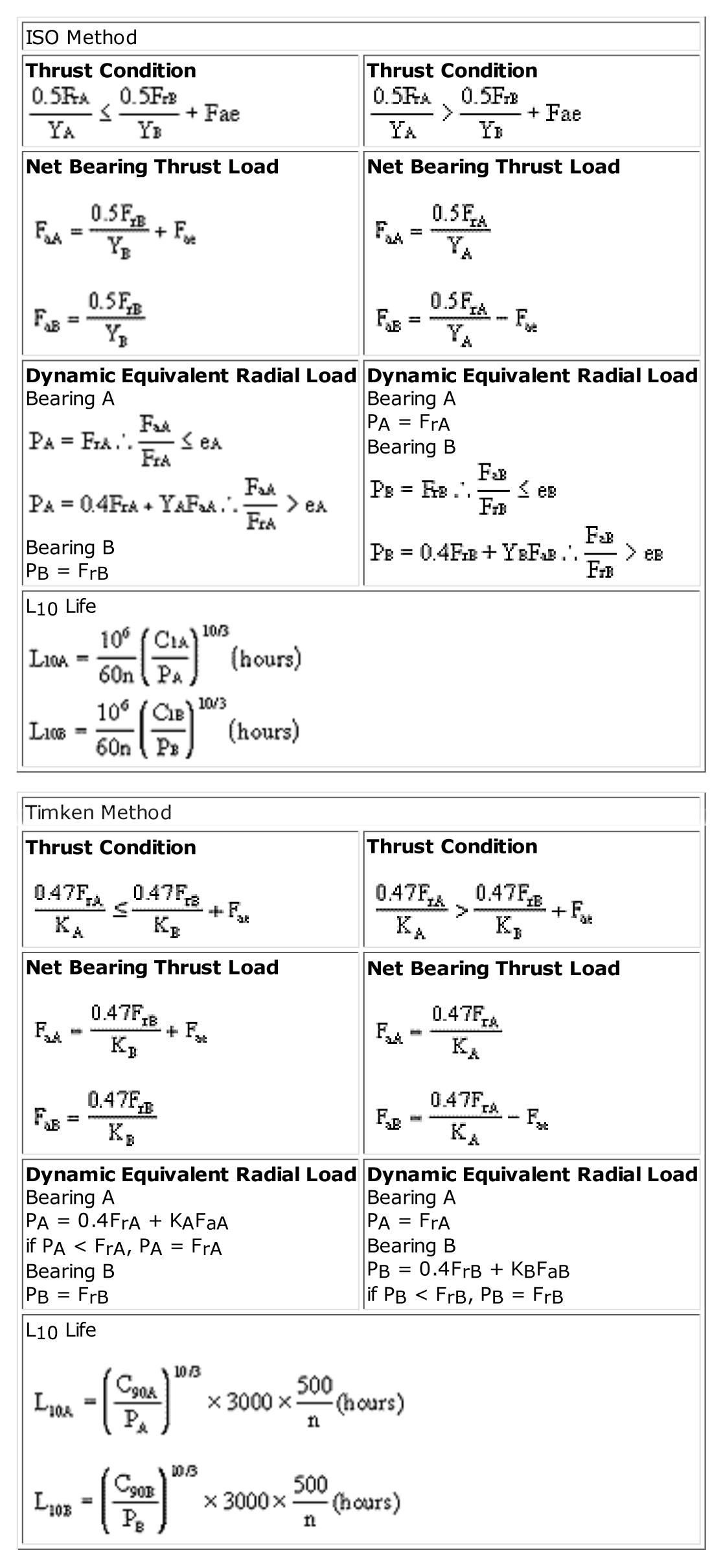
Tapered roller bearings are ideally suited to carry all types of loads : radial, axial or any combination. Due to the tapered design of the bearing, a radial load will induce an axial reaction within the bearing which must be equally opposed to avoid separation of the inner and outer rings. The ratio of the radial to the axial load (external axial load and induced load), the setting and the bearing included cup angle determine the load zone in a given bearing. This load zone is defined by an angle which delimits the rollers carrying the load. If all the rollers are in contact and carry the load, the load zone is referred to as being 360 degrees. In the case of combined loads, a dynamic equivalent radial load must be accounted for the complete the bearing life calculation and determine bearing life. The equations presented below give close approximations of the dynamic equivalent radial loads. More exact calculations using computer programs can be made that take into account such parameters as bearing spring rate, setting and supporting housing stiffness.
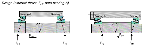
Combined radial and thrust load
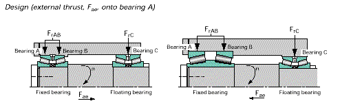
 Two-Row Bearing
Thrust Load Only
Now that you know how to calculate bearing life, learn “How to Extend Bearing Life.”
Related Articles
Hydraulic System FMEA Made Easy
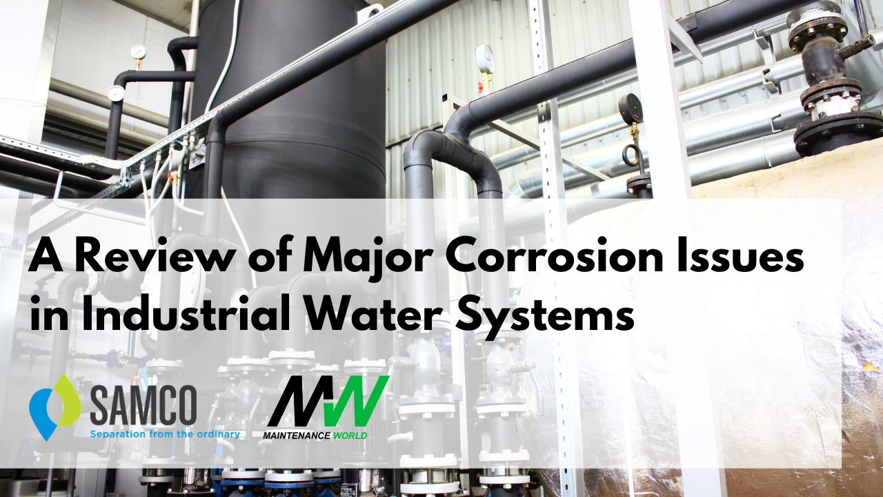
Major Corrosion Issues in Industrial Water Systems – Part 1
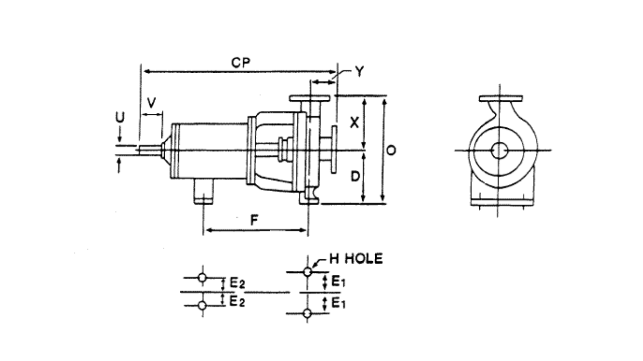
The ANSI Pump Standard 14-5

How Can I Extend the Performance Range of Standard Cartridge Mechanical Seals?
Cavitation
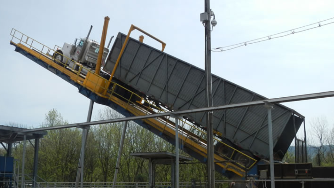
10 Steps to Pump Reliability - Part 2