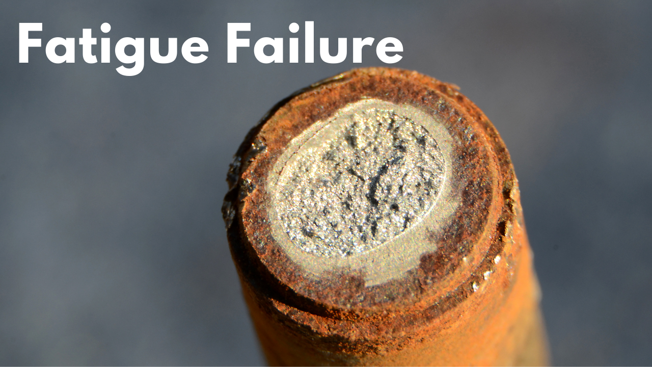
Metal Fatigue Failure
Mike Sondalini, with permission of BIN95 Industrial Training
Posted 03/30/2023
Abstract
Metal fatigue failure. Metal fatigue is the common name used to describe the unexpected failure of metal parts by progressive fracturing while in service. The article is a basic introduction to the mechanism of metal fatigue failure. An introduction into accepted theories is provided and relevant design practices to reduce metal fatigue are presented and explained.
Keywords: cyclic failure, stress concentration factor, microstructure, micro crack, alternating stress, stress relieve, stress point, cycles to failure, infinite life.
What is Metal Fatigue?
Metal fatigue is directly related to the number of stress cycles undergone by a part and the level of stress imposed on the part. Studies have shown that infinite life for a metal part is possible if the local stresses in the part are kept below well-defined limits. Fatigue failures increase if parts have stress raising contours or if stress raisers such as notches, holes and keyways are put into the part. There is also a relationship between a metal’s ultimate tensile strength (highest point on the stress – strain curve of Figure 1 in ‘Stress in Metals’ article) and hardness and its ability to handle fatigue loads. The higher the tensile strength and hardness the more likely it will fatigue if it is subject to high fluctuating loads.
Theory of Fatigue Failures
The generally accepted explanation for the mechanism of metal fatigue is based on dislocation theory. This theory was covered in the article on ‘Stresses in Metals’. Basically the theory says that the atomic arrangement in the crystals of a metal is imperfect and contains numerous missing atoms. The missing atoms create gaps, which cause massive stress raisers. When the metal is put under load the stress raising gaps shear their way through the crystal grains and collect together. When enough atomic gaps collect together a microscopic crack is formed or nucleated. If the load is increased the initial crack opens up. If the load fluctuates from a minimum to maximum near the metal’s load carrying limit new microscopic cracks expand out from the site of the first micro crack. Each crack becomes a stress raiser for the next one and they continue to develop until the remaining metal can no longer take the load and it suddenly fails.
Stress v. Life Cycle Curves
A great deal of fatigue load testing has been done with a wide range of metals. From these tests graphs of tensile strength verses number of cycles to failure have been developed. An example of one for wrought (worked) steel is shown in Figure 1.
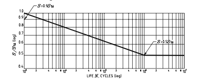
The vertical scale on this log-log plot shows the applied stresses as a proportion of the steel’s ultimate tensile stress ‘Su’ while the horizontal scale is the number of stress cycles to failure. The left hand sloping line tells us is that a steel part put under high cyclic loads producing stresses in high proportion to its ultimate tensile stress will fail after a given number of cycles. Whereas the right hand side of the curve indicates that if cyclic stresses are maintained below a definable limit the part will have infinite life. The curve also tells us that a steel part made of this metal will fail if it has just one load cycle with a stress greater than its tensile strength. (Like when a small bolt snaps-off if over-tightened) It will also fail in less than one thousand cycles if the imposed stresses are 90% or more of the tensile strength. But if the stresses are kept below half of the tensile strength it will never fatigue.
Designing for Fatigue Conditions
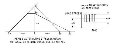
Metal fatigue occurs when parts break at a weak point after a period of time in service due to cyclic forces producing fluctuating stresses. Knowing a part will be subject to fluctuating loads requires the designer to design the part for that condition. Using the known ultimate tensile stress and yield stress (stress at which the metal first starts to permanently deform, about 80 – 90% of tensile stress) of a metal the designer constructs a stress limiting envelope as in Figure 2. The part is then designed so that the cyclic loads applied to it keep the relevant stresses within the envelope.
Stress Concentration Factors
Virtually all fatigue failures occur on the outside surface of a part at stress concentration points or stress raisers. Examples are grooves, fillets, holes, threads, keyways, splines, welds, etc. The designer must take into account the affect of these stress raisers if the part is to provide long, trouble free service. The effect a stress raiser is directly related to the smallness of its radius. As with the micro cracks mentioned earlier which promote fatigue failure, the smaller the radius of a stress raiser, the more focused and larger are the resulting stresses. Interestingly metals with high ductility suffer little from stress raisers. The explanations being that the metal deforms and in so doing the stress induced by the stress raiser is limited to the yield stress.
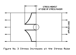
Figure 3 shows a plate with a hole. The effect of the hole on the stress levels across the plate is shown by the stress curve rising as it gets closer to the hole. Every stress raiser acts to concentrate stresses at the location of the imperfection.
Stress factors for different geometry of parts have been determined and charted. The designer uses the stress factors to reduce the allowable load on the part (The stress concentration factors make the design envelope of Figure 2 smaller). If the calculations indicate that the part will fail, the designer has the choice of increasing part size, changing to a higher tensile strength metal or surface treating the part to greatly reduce the chance of fatigue cracks developing.
Surface Finish and Surface Microstructure Treatments
Since fatigue failure usually starts at the surface of a part where the applied loads produce maximum stresses, it becomes important to consider the surface finish and surface microstructure. We know that tensile stresses promote and compressive stresses impede fatigue failure. Compressive surface stresses increase fatigue load carrying capacity. If the part’s surface can be put into compression it will have less chance of metal fatigue failure.
When the surface of a part is under tensile stress, microscopic surface cracks are most likely to develop at stress raising locations. If the stress raisers were not present the part could sustain greater load. Alternatively, if the metal’s outer layer had higher tensile properties it would take greater stresses to nucleate a crack site. Great improvements in a part’s strength can be made by treatments that strengthen the surface material.
Surface finish is measured by surface roughness (groove valley to crest height). The less the roughness, the smaller the microscopic grooves and the larger the valley radius becomes in proportion to the height of the groove. Larger radii decrease the effect of the stress raiser and increase the fatigue stress at which a part fails. Polished, ground and machined surfaces are best. Forged and cast parts are worst due to poor surface finishes.
Surface microstructure can be altered in a number of ways. One method is by surface carburising in which carbon is added to the outer layer of a part to increase hardness. Another technique is cold working the surface to deform it and put it into compression. The two most often used surface compression methods are shot peening and cold rolling of the surface. In both cases the outer metal layer is forced to yield and the residual stresses resulting from the deformation cause the surface to go into compression. An example is the rollers on roller chain. The third way is to case harden the surface of suitable metals by heat treatment and transform the microstructure of the outer layer to one with better fatigue resistant properties.
Recommended Practices to Increase Fatigue Life
When designing and making a part there are a number of factors to consider in order to get maximum fatigue life.
- Avoid sharp corners. Use generous radii to reduce stress concentration levels.
- Avoid abrupt changes in cross-section. Remove metal so there is a smooth transition between cross-sections.
- Make machined surface finishes as smooth as possible. Scratches perpendicular to the applied loads become stress raisers. Use fine emery cloth to polish the surface.
- Welding needs to be of good quality with no inclusions, gas holes (porosity) or worm holes. The weld fillet should have a nice contour and be completely filled.
- Welds alter the metallurgical properties of a metal (rapid cooling rates cause large grain growth) and the parent metal is weakened in the heat-affected zone (HAZ). The HAZ extends below the weld and fatigue cracks can develop under the surface. If the part is critically loaded it will be necessary to heat treat the HAZ to modify the metal’s microstructure.
- Surface treat to produce compressive forces or appropriate metallurgical properties in the outer layers of those parts which will be cyclically loaded at stress raising locations.
- Select materials with good fatigue resistant metallurgical properties. Use small grained, homogeneous microstructure, high tensile stress with some degree of ductility.
- If a part is scratched or has a machining mark, polish the defect down to its base and blend the sides into the parent part.

Related Articles
Fatigue Failure 101

The Keys to Solving Fatigue: The Silent Killer

Managing Today's Castles with InMapz
Electric Motor Problems
Studying Fractures: Recognizing and Understanding Failure Modes