The Pump Impeller: Pump Life Extension
Mike Sondalini, with permission of BIN95 Industrial Training
Posted 02/28/2023
Abstract
Pump life extension – the pump impeller. A spinning pump impeller provides the means to draw incoming product through the pump, energise it, and then force it out under pressure. The impeller converts the electrical energy from the motor into hydraulic energy of the liquid. It does this by taking the liquid into the center of the impeller and flinging it outward at high speed. To efficiently continue to do this the impeller must remain in the same condition as it was when first installed. If the impeller deteriorates the conversion from electrical to hydraulic energy becomes inefficient. Power is wasted, flow and pressure fall and the pump cannot do its designed duty.
Purpose of a Centrifugal Pump Impeller
A standard centrifugal pump impeller is constructed of a group of elongated, solid-walled chambers attached together in the shape of a circular ring. The ring is spun quickly and the liquid that enters the inside end of the chambers is flung out at high speed from the other end. Figure No. 1 shows a section through centrifugal pump wet-end showing regions of low and high pressures.
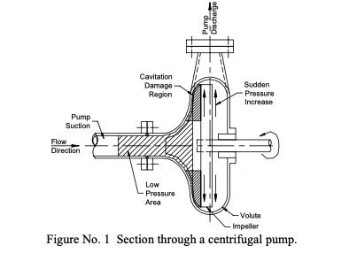
The longer the chamber (i.e. a bigger diameter), the faster the liquid leaves the ring for a given speed. Alternately the faster the ring is spun the faster the liquid is flung out. High tip speeds produce higher pressures. The pressure generated in a centrifugal pump is the result of the high-speed liquid hitting and stopping at the volute wall and so changing its energy of motion (momentum) into pressure energy. The pressure then forces the liquid out the discharge nozzle.
To stop the pressure from returning to the suction inlet and back through the chambers, the gap between the impeller and the volute is made very small at the suction nozzle inlet. Usually wear rings are fitted to the impeller. When the wear from the small amount of leakage that does occur gets too bad they are changed over for new.
What Happens Inside the Pump Impeller?
As liquid is flung out from an impeller it leaves a space behind. This space is taken up by the particle of liquid immediately following. By flinging one lot of liquid out, it forces new liquid to be drawn in to take its place. Spinning the impeller creates a low pressure at the center inlet and the pump seems to ‘suck’ liquid from a distance.
In fact the pump does not ‘suck’. Rather the pump inlet pressure is lower than the pressure at the supply point and the higher supply pressure tries to equalise the pressure imbalance. The high pressure flows to the low pressure. As long as the pump keeps creating the low-pressure region at its impeller inlet the liquid will flow into it. The pressure does not even need to be a vacuum (i.e. less than atmosphere pressure); it only needs to be at a lower pressure than the supply point pressure.
Properties of the Liquid
Successful operation of the impeller is also dependent on the properties of the liquid being pumped. The three main liquid properties affecting the impeller are the viscosity (slipperiness), the corrosiveness and the pressure at which the liquid becomes a gas (vapour pressure).
Viscosity
High viscosity means a more-thick liquid. As viscosity rises the liquid does not move as easily and tends to stick to itself and shear only at the point of the movement. Imagine pumping grease through a centrifugal pump! The grease would not want to move but instead the impeller would just spin and tear through the grease immediately in contact with it. Where appropriate heating a viscous liquid to make it more ‘flow-able’ can lessen this problem.
Corrosiveness
Chemical attack by the liquid on the impeller will destroy the impeller. In such situations it is necessary to use impeller materials that do not chemically react with the liquid at the process conditions in the pump or to coat the impeller with a protective surface.
Vapour Pressure
A liquid can turn to gas (vapour) either by adding heat and boiling it at a given pressure (like in a saucepan on a stove) or by bringing the pressure low enough to ‘boil’ it at the surrounding temperature (water boils at lower temperatures in the mountains than at sea level).
If the suction pressure at a pump impeller inlet were so low that the liquid ‘boiled’ into a gas/vapour then bubbles would appear in the liquid stream (See article 232 Centrifugal Pump Cavitation). The bubbles at low pressure would then move into the spinning impeller chambers and suddenly experience high pressure (see Figure No. 1) as it moves through the impeller. The bubbles implode and eject a shot of high velocity liquid at the impeller and gouge a bit of it out. Cavitation destroys impellers.
If the pressure were brought even lower the liquid would instantly become vapour in the suction pipe as it approached the impeller. The vapour would expand and fill the pump volute. A centrifugal pump cannot move gas so the pump would stop pumping. The vapour would then be under higher pressure from liquid in the discharge and suction pipes flowing into the pump. The vapour cannot exist at that pressure and it dissolves back into the liquid. The liquid would again flow to the pump. With liquid present and the impeller spinning the pump starts to pump. The pressure again falls at the impeller inlet and the liquid flashes to vapour a second time. The cycle repeats and the pump would deliver slug flow or ‘vapour lock’.
It is critically important that the inlet pressure to the impeller never falls below the vapour pressure. If you pump a liquid containing dissolved gas (like carbon dioxide in beer) the lowest limiting pressure may not be the liquid vapour pressure. It may instead be the dissolution pressure of the gas. Keep suction pressure above the dissolution pressure.
Modes of Centrifugal Pump Impeller Failure
There are numerous ways an impeller’s performance can be affected. Listed below are some of the more common ones.
Wear: Abrasion and erosion can occur when solid particles (as in slurry) are present. It may be necessary or select wear resistant materials. If solid bits of metal, stone or rubbish from the process are present it is critical to fit a strainer before the pump AND clean it out regularly before it blocks up and the pump starves and cavitates.
Cavitation/vapour lock: As noted above keep the pressure at the impeller inlet above the vapour pressure. Keep the suction flow velocity low – use big bore pipes; keep suction pipe insides clear of obstructions; clean strainers often. Pressurise the suction supply – put the supply tank way above the pump; put additional pressure onto the surface of the liquid in the supply tank (but don’t split the tank) and slow the pump. Cool the liquid so it will not be hot enough to ‘boil’ at the impeller inlet pressure.
Blockages/objects: Solids can block the impeller vanes. Chunks of wood can get stuck in the vane passage, gloves, foam cups, dropped tools, nut and bolts, tank floats, parts of instruments, etc may not pass through the impeller. An in-line strainer is a must in such cases. An alternative is to relocate the supply tank outlet nozzle higher up the tank and let the solids settle to the bottom, and draw liquid from the cleaner level. The rubbish at the tank bottom can be drained out a lower nozzle or the tank manually cleaned.
Loss of running clearances/recirculation: If the wear ring clearance between impeller and volute becomes too great the liquid will recirculate from the high pressure at the impeller outlet to the low pressure at the inlet. The flow from the pump falls because liquid is instead drawn back into the suction inlet and just goes in circles.
Material of construction/corrosion: The impeller must be impervious (unaffected) to chemical attack.
Change of service duty: If a pump is moved from one position to another or from one service to a different service, it may not pump. Each impeller is sized to a specific flow and pressure. If the pump is move from its original duty it must be engineered for the new duty (See article 112 Changing the Service Duty of a Pump).
Direction of rotation: The vanes on centrifugal pump impellers are designed to rotate in only one direction. They can still generate pressure if turned the wrong way but the pressure and flow are very much less that if they were going the right way. Changing any two phases on a 3-phase electric motor reverses its rotation.
Air locks: Trapped gas and air around an impeller will stop it from pumping. If the impeller is spinning inside a volute with the top part of the volute full of gas the ejected liquid is not compressed against the volute wall and cannot convert its velocity into pressure. The pump will run but nothing will come out. The air, gas or vapour in the top of the volute must be removed.
If the air lock is in the suction pipe the pump will try to draw liquid and pull the air with it. However the air is always at the top of the pipe and fills part of the pipe. The liquid must then flow in the remaining part of the pipe. If this area of pipe is to small then not enough liquid will get to the pump and it will stop pumping till more arrives. Slug flow develops. In the worst air lock case no liquid gets to the pump. Air, gas or vapour must be removed.
Best practice is to slope the suction pipe so that any gas caught inside it finds a way to naturally flow through to the pump and out the pump discharge line. Or else find ways to flow back into the supply tank and bubble up to the surface of the liquid. Failing that it is necessary to install valves along the pipeline that can be opened to vent out the trapped gases until liquid appears.
Buy pumps with vertical center discharges instead of side discharges as gases can get trapped in the top circular portion of the volute. Or rotate the volute and piping to have the outlet at the high point.

Related Articles

The Japanese Path to Maintenance Excellence

OEE: Overall Equipment Effectiveness
Centrifugal Pump Troubleshooting
Maintenance Equipment: Basic of Centrifugal Pumps