Electric Motor Problems
Mike Sondalini, with permission of BIN95 Industrial Training
Posted 01/26/2023
Abstract
Electric motor problems. This article presents a basic explanation of electric motor construction and operation along with twelve problems that can be encountered with their use. Most electric motors in industrial equipment are three phase alternating current induction motors. Induction is the creation of an electric current across a gap. Two types of induction motors are commonly used: squirrel-cage and wound-rotor. The names come from the way they are built.
Keywords: motor characteristics, mounting, frame size.
Induction Motor Design
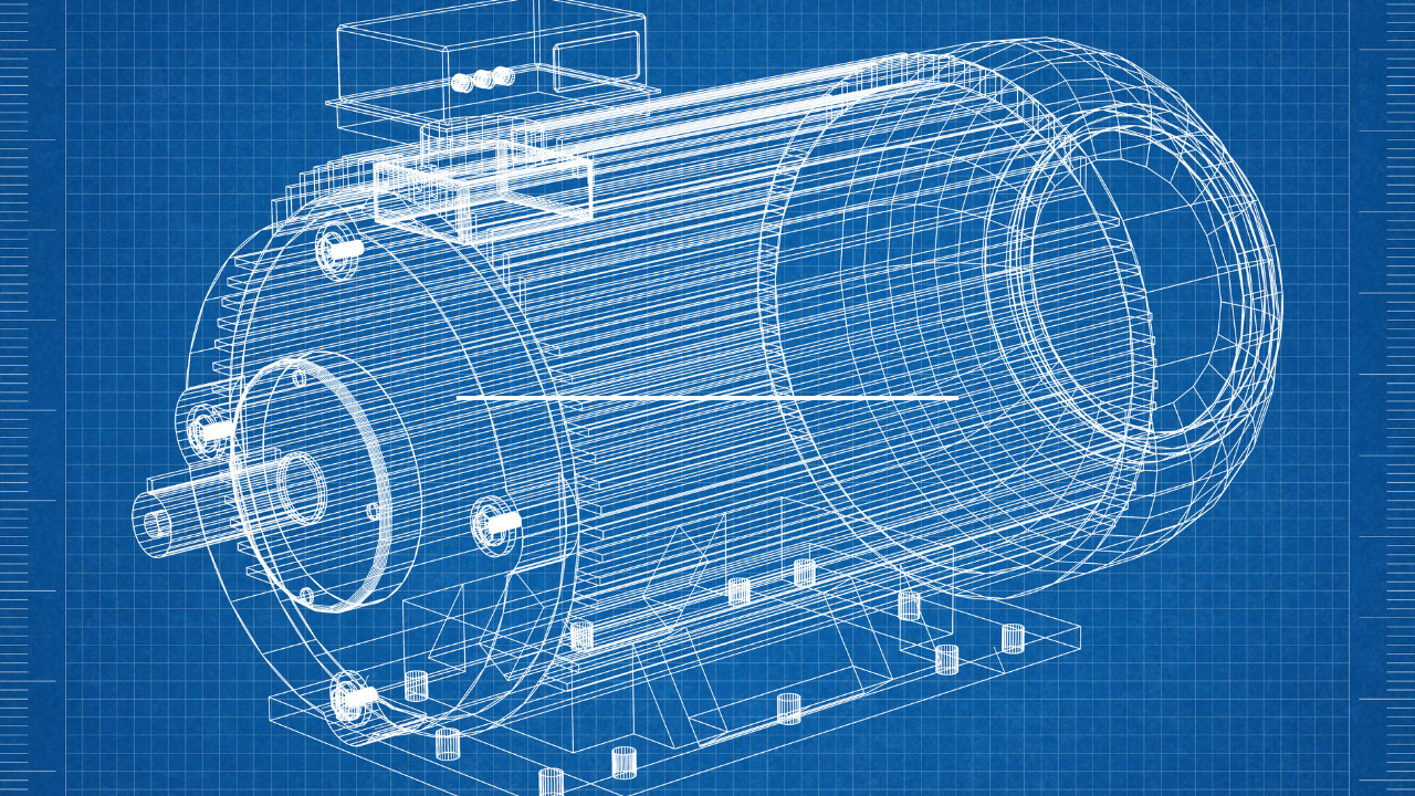
An electric motor consists of an iron rotor wheel mounted on a shaft, supported by bearings at each end, spinning within a multi-coil cage of wire called a stator. Copper or aluminium bars are imbedded in the outside surface of the rotor and connected together to form a circuit. The wire windings in the stator are arranged to form an electromagnet. Figure 1 shows a simplified motor design. The electric currents flowing through the outside stator coils create a magnetic field through the rotor while inducing an electric current in the rotor bars.
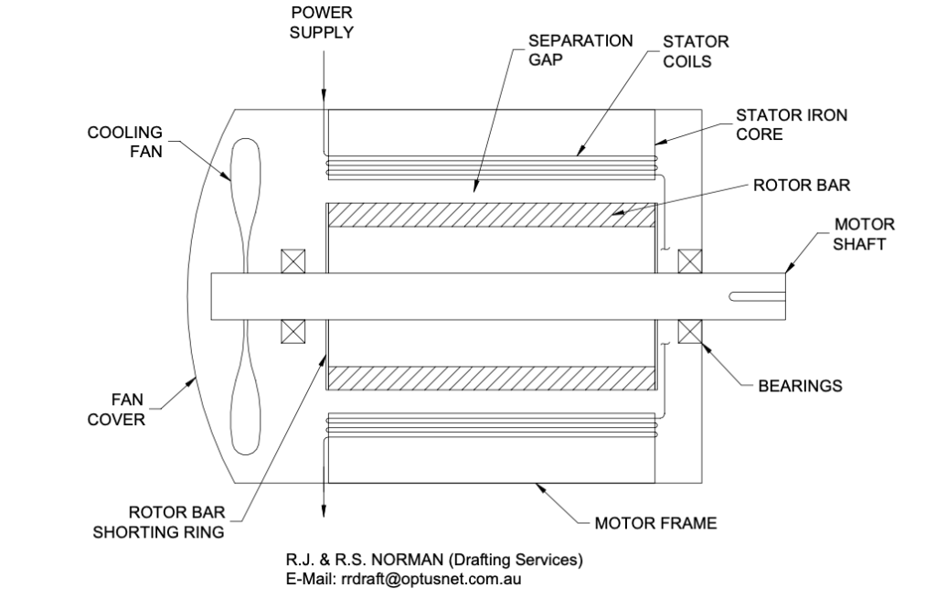
When alternating current (AC) flows through the stator coil, reciprocating north and south magnetic poles are created at the ends of each coil. At the same time, like a transformer, the electric fields in the stator coils also create an electric current in the rotor. When an electric current is cut by a moving magnetic field a reaction force occurs in the current carrying conductor. The bars in the rotor, now induced with current, react in response to the magnetic field and force the rotor to turn. The alternating magnetic field is then created in the neighbouring coil and the rotor continues to turn.
For motion to be induced on the rotor the electric carrying conductor must cut the magnetic field. This means the rotor must move slower than the cycling magnetic field. It is only by cutting through the lines of magnetic force that torque is generated on the rotor. An electric motor will always run at a slightly slower speed than the cycling magnetic field.
The motor speed depends on the number of separate magnetic fields created by the coils in the stator. A two-pole motor has one coil and one magnetic field arranged around the stator, a four-pole motor has two coils arranged around the stator with each winding placed between the other in sequence. A six-pole motor has three coils with the windings spaced in sequence around the stator, and so on.
Characteristics of Electric Motors
The torque generated on the rotor and attached shaft results from the interplay of several electrical, magnetic and physical variables that alter with the speed of the rotor.
When choosing an electric motor it is necessary to consider if the behavior of the load attached to the motor is suited to the load characteristics of the electric motor. A rotor begins from rest and must come up to full speed while dragging its load around with it. The electrical currents that occur within a rotor going through start-up and operation vary greatly and influence the motor load carrying capacity.
Electric Motor Problems
Below are a number of problems that are often encountered when using electric motors.
- Water ingress into the motor will go between the stator coils or into the terminal box and short circuit and burn out the motor. Water must never be allowed to get into a motor. If motors are to be used in wet areas that must be of the correct ingress protection (IP) rating.
- Overheating can occur from undersizing the motor, insufficient cooling at low speed when using variable speed drives (VSD), changes to the load on the motor such as jammed equipment and hot ambient conditions. Temperature detection (thermistor) and automatic shut down devices can be installed. Attaching a separate booster fan to aid the motor fan solves the overheating problem when a VSD is used to control the motor speed.
- Bearing failure on motors can be an indication of the incorrect bearings for the application. A motor mounted vertically needs different bearings to a motor mounted horizontally. A motor driving a large or multi-belt drive will require bearings that handle big radial loads. A motor bolted to a distorted base plate will twist (See Soft Foot). Check bearing types with the manufacturer.
- Motors in-store or not in operation for long periods of time get false brinelled bearings where the bottom bearings etch into the shaft. Turn the motor shaft a quarter turn monthly. Bearings in motors in- store exposed to low vibrations through the ground can brinell. Sit motors on a sheet of 3-mm rubber to insulate them from ground borne vibrations.
- Burnt windings imply a short circuit either within the motor or within the power supply circuit for the motor. Over-current protection can be installed as part of the power supply circuitry.
- Dust ingress into the stator coils or the terminal housing leads to short-circuiting. If the motor is to be in a dusty environment keep the immediate area around the motor clean or use dust ingress protection (DIP) methods.
- Hazardous area motors must comply with the type of hazard in the area. Motors in flammable vapours like gasoline, in explosive vapour atmospheres and in explosive dust environments such as grain dust all need to be rated and protected for the specific location. There are various methods of hazardous area motor protection but they are not transferable across hazard types. For example a motor protected against an explosive dust is not suitable to use in a flammable environment.
- Temperature ratings of housings vary. The motor housings get hot under operation and there are six different temperature ranges available for motors depending on the environment it must work in.
- Running in reverse is a common problem. Changing over any two terminal leads changes the motor direction. Always test run a motor to check direction after it is wired-up. Separate the shaft coupling to protect the driven equipment from damage if necessary. Automatic current reversing relays are available to provide the correct motor direction.
- Shaft misalignment will destroy bearings well before their full working life. The motor shaft must be directly in-line with the shaft it is driving. This can only be achieved by using precision alignment techniques such as laser or dual dial indicators. The motor shaft must turn along its full length to within 0.05 mm (0.002”) of the true center of the driven shaft. This minimises the vibration, forces and loads that planetary rotation of one shaft in respect to the other would create.
- Soft foot occurs when the motor feet are bolted down out of level. If all feet are not in the same plane when pulled down on the base plate the motor housing twists and the bearings are distorted. Put a straight edge across the base plate and measure gaps with feeler gauges. Place the motor on a flat, machined bed and check the gap under each foot. Put 316 stainless steel shims under the high feet to level them when bolted down.
- Wrong motor mounting or housing type leads to frustration. Motors are either foot mounted or flange mounted. They come in various frame sizes and designs and the correct choice and delivery is needed.
Need to troubleshoot your electric motor problems? Read more to learn how!
Author Mike Sondalini with permission of BIN95 Industrial Training

Related Articles

The Japanese Path to Maintenance Excellence

OEE: Overall Equipment Effectiveness
A Guide to Matching Electric Motors with Hydraulic Power Units
Electrical Motor Diagnostics: Impact of Electric Motor System Maintenance and Management
Maintenance and Troubleshooting of Electric Motors
Developing an Effective Electric Motor Testing Program

Electric Motor Testing Certification**