Effective Predictive and Pro-Active Maintenance of Pumps
John Piotrowski
Maintenance of Pumps
Keeping pumps operating successfully for long periods of time requires careful pump design selection, proper installation, careful operation, the ability to observe changes in performance over time, and in the event of a failure, the capacity to thoroughly investigate the cause of the failure and take measures to prevent the problem from re-occurring. Pumps that have been: properly sized, are dynamically balanced, that sit on stable foundations with good shaft alignment, with proper lubrication, where operators start, run, and stop the machinery with care and where the maintenance personnel observe for unhealthy trends that begin to appear and act on them usually never experience a catastrophic failure.
This is true with a large percentage of pumping systems but, it is definitely not true with all of them. Frequently pumps are asked to operate way off their best efficiency point, or are perched on unstable baseplates, or run under moderate to severe misalignment conditions, or were lubricated at the factory and never see another drop until the bearings seize, and vibrate to the point where bolts come loose. When the unit finally stops pumping, new parts are thrown on the machine and the deterioration process starts again with no conjecture as to why the failure occurred.
Recently a supervisor at a pharmaceutical company who has been trained in root cause failure analysis stated that when a failure occurs on a piece of machinery it should be treated as a police crime scene where corrective action is not initiated until all the evidence is gathered by the scientific crime lab personnel to find the primary source of the malady. Until the real criminal is apprehended and banished, the crime is most likely to occur again and again. Take a moment to reflect on how many times you and your organization have thoroughly investigated a failure until you found the primary cause(s).
The Four Maintenance Philosophies
If you work long enough in industry, you may get an opportunity to observe all the different “styles” of maintenance. How maintenance organizations operate usually fall into four different categories:
• Breakdown or Run to Failure Maintenance
• Preventive or Time Based Maintenance
• Predictive or Condition Based Maintenance
• Pro-Active or Prevention Maintenance
Briefly, here’s what each one is about.
Breakdown or Run to Failure Maintenance
The basic philosophy is to allow the machinery to run to failure and only repair or replace damaged equipment when obvious problems occur. Studies have shown that the costs to operate in this fashion are about $18 per horsepower per year. The advantages of this approach is that it works well if equipment shutdowns don’t affect production and if labor and material costs don’t matter. Where would this apply?
The disadvantages are that the maintenance department perpetually operates in unplanned / ‘crisis management’ maintenance activities with unexpected production interruptions and the plant must have a high inventory of spare parts to react quickly. Without a doubt, it is the most inefficient way to maintain a facility. Futile attempts are made to reduce costs by purchasing “cheap” parts and hiring “cheap” labor further aggravating the problem. Frequently the personnel are overworked and understaffed arriving at work each day to be confronted with a long list of unfinished work and a half dozen new “emergency” jobs that occurred while they were at home in the evening. It is not uncommon to send someone out to work on an emergency job first thing in the morning and by 10 o’clock, half way through the job, stop their progress and send them on a new “higher priority” emergency job.
Despite the wonders of modern life in the new millennium, I see many places like this. I hope you are not in one of them.
Preventive or Time Based Maintenance
This philosophy consists of scheduling maintenance activities at predetermined time intervals where you repair or replace damaged equipment before obvious problems occur. Done correctly, studies have shown that the costs to operate in this fashion are about $13 per horsepower per year. The advantages of this approach is that it works well for equipment that does not run continuously and the personnel have enough knowledge, skill, and time to perform the preventive maintenance work.
The disadvantages are that the scheduled maintenance may be done too early or too late. It is quite possible that reduced production could occur due to potentially unnecessary maintenance. In many cases there is a possibility of diminished performance through incorrect repair methods. I have witnessed perfectly good machines disassembled, good parts removed and discarded, and then new parts improperly installed. For some, squirting grease into bearings every month is their idea of a preventive maintenance program.
Predictive or Condition Based Maintenance
This philosophy consists of scheduling maintenance activities only if and when mechanical or operational conditions warrant by periodically monitoring the machinery for excessive vibration, temperature, lubrication degradation or observing any other unhealthy trends that occur over time. When the condition gets to a predetermined unacceptable level then the equipment is shut down to repair or replace damaged components in the equipment to prevent a more costly failure from occurring. In other words “DonÕt fix what is not broke”. Done correctly, studies have shown that the costs to operate in this fashion are about $9 per horsepower per year. The advantages of this approach is that it works very well if personnel have enough knowledge, skill, and time to perform the predictive maintenance work. The repairs to equipment can be scheduled in an orderly fashion and it allows you some lead time to purchase materials for the necessary repairs reducing the need for a high parts inventory. Since maintenance work is only performed when it is needed, there is a likely increase in production capacity.
The disadvantages are that maintenance work may actually increase if the personnel improperly asses the level of degradation in the equipment. To observe the unhealthy trends in vibration, temperature, or lubrication, this approach requires the facility to procure equipment to monitor these parameters and provide training to in-house personnel. The alternative is to outsource this work to a knowledgeable contractor to perform predictive / condition based duties. If an organization had been running in the breakdown / run to failure mode and / or the preventive maintenance style, the production and maintenance management must conform to this new philosophy which can be problematic if the maintenance department is not allowed to purchase the necessary equipment, provide adequate training to the people to learn the new techniques, are not given the time to collect the data, or are not permitted to shut down the machinery when problems are identified.
Pro-Active or Preventive Maintenance
This philosophy utilizes all of the predictive / preventive maintenance techniques discussed above in concert with with root cause failure analysis to not only detect and pinpoint the precise problems that occur but to insure that advanced installation and repair techniques are performed including potential equipment redesign or modification to avoid or eliminate problems from occurring. Done correctly, studies have shown that the costs to operate in this fashion are about $6 per horsepower per year. The advantages of this approach is that it works extremely well if personnel have enough knowledge, skill, and time to perform all of the required activities. As in the predictive based program, repairs to equipment can be scheduled in an orderly fashion but then additional efforts are made to provide improvements to reduce or eliminate potential problems from repetitively occurring. Again, repairs to equipment can be scheduled in an orderly fashion and it allows lead time to purchase materials for the necessary repairs reducing the need for a high parts inventory. Since maintenance work is only performed when it is needed, and extra efforts are put forth to thoroughly investigate the cause of the failure and then determine ways to improve the reliability of the machinery, there can be a substantial increase in production capacity.
The disadvantages are that this requires extremely knowledgeable employees in preventive, predictive, and prevention/pro-active maintenance practices or to outsource this work to a knowledgeable contractor who works closely with the maintenance personnel in the root cause failure analysis phase and then assist in the repairs or design modifications. This also requires procurement of equipment and properly training personnel to perform these duties. If an organization had been running in the breakdown / run to failure mode and / or the preventive maintenance style, the production and maintenance management must conform to this new philosophy which again can be problematic if the maintenance department is not allowed to purchase the necessary equipment, provide adequate training to the people to learn the new techniques, are not given the time to collect the data, are not permitted to shut down the machinery when problems are identified, are not given the time and resources to conduct the failure analysis, and then do not modify the component or procedure to increase the reliability.
What to do Before Rebuilding or Replacing a Pump
Effective problem identification and problem avoidance requires a rigorous investigation process. When a pump failure occurs, it is very tempting to remove the pump, replace the defective parts (or the entire pump), install the new or rebuilt unit, and get the unit back on line as quickly as possible. However if several checks are not made during the removal and disassembly process, important clues as to the cause of the problem will be overlooked. Below is a recommended checklist that should be done when any pump is removed from service to assist in identifying the source of the failure. In fact, it may not be a bad idea to preform many of these checks on an annual basis.
During the disassembly process, the following things should be checked:
1. Was the coupling guard rubbing against the shaft or the coupling?
2. For mechanically flexible couplings (e.g. gear, metal ribbon, chain), is there grease or oil on the inside of the coupling guard and on the baseplate? If so, did it come from the coupling, the bearings on the motor or the pump, or someplace else?
3. Once the coupling guard is removed, does the flexible coupling show any obvious signs of distress? Don’t take it apart yet, just visually inspect it slowly rotating the shaft by hand. For example, did it appear that it was running hot or are any of the coupling bolts loose? If it is an elastomeric type coupling, does the rubber appear to be cracked or is there rubber powder on the baseplate? If it is a flexible disk type coupling, are the disk packs cracked or show signs of cyclic fatigue? Is there an excessive amount of “backlash” across the coupling? Does the coupled shafts seem to turn easily or at least consistently through the entire 360 degrees of rotation or are they very difficult to rotate or do they rotate smoothly for part of the rotation and then seems to bind for the rest of the rotation?
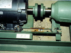
Notice the rubber dust under the flexible coupling on the concrete floor. Not a good sign. Oh, and by the way, DO NOT use unistrut to mount rotating machinery to a baseplate like is shown here please!
4. Prior to disassembling the coupling, capture a set of shaft alignment measurements. It really does not matter what type of alignment method or tool is used to capture the measurements. What is the the amount of misalignment in mils per inch? Was the pump being subjected to run under a slight (0.1 to 2 mils/inch), moderate (2.1 to 10 mils/inch) or severe (10+ mils/inch) misalignment condition? Since a good Pro-Active maintenance program requires that you keep records of alignment on all the rotating machinery in your facility, compare the as found alignment to the last final alignment on the unit. Has the alignment shifted? If so, how much and what caused the shift? (easy question to ask, but usually quite difficult to answer).
5. Now begin to disassemble the flexible coupling. Were all the bolts tight? Are any parts missing? If the coupling is a mechanically flexible type (gear, metal ribbon, chain, U-joint, etc.), is there any lubricant still in the coupling? If so, does it look like fresh grease or oil or is it discolored? If it is grease, did the grease centrifugally separate into oil and its base (i.e. is there a build up of thick brown or gray sludge or powder in the coupling?). If possible, scrape off some lubricant for analysis then wipe all of the grease away with rags and solvent if necessary. Inspect the coupling for excessive wear. If you arenÕt sure what excessive wear would look like on that particular coupling, get a new coupling and have it there for visual comparison. If the coupling is an elastomeric type, is the rubber hard and no longer pliable? Does the elastomeric element appear to be worn or is it cracked? How long has the elastomer been in service? Are the set screws still in place and were they loose? If the coupling is excessively worn, it will probably have to be replaced. Use an appropriate puller to remove the coupling hubs, do not beat them off with a hammer. If the coupling hubs had an interference fit and heat is required to remove them, try not to heat the hub above 275 degrees F. If you have to get them “cherry red” to remove them, throw them away and replace them since you probably changed their metallurgical characteristics or thermally warped them. In some cases, coupling hubs are so tight or have “rusted” to the shaft that they have to be carefully cut off. If it appears that the coupling hub was hit with a hammer before, it is possible that the shaft was bent. Check item 8 below.
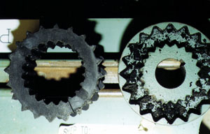
Here’s the coupling shown above after it was removed. This unit had been operating with 20.5 mils/inch of misalignment for about 4 months. The rubber insert had already been changed once but the mechanics did not bother to align the unit.
6. Visually inspect the pump for any obvious problems such as loose foot bolts, loose pump casing bolts, cracked casing, low lubricant level, loose shim packs or missing shims, leaking mechanical seal, leaking oil seals, or discoloration in the shaft.
7. Determine if there is an excessive amount of shaft “freeplay”. This is fairly easy to do and can tell you if there are potential bearing problems in the pump or driver. Attach a fixture on the driver shaft, span across the coupling (engaged or disengaged) and place a dial indicator on the top of the pump shaft (or coupling hub) and zero the indicator. Lift the shaft from underneath and observe the dial indicator. If the pump shaft is supported in rolling element bearings, you should not see any more than 1 mil of movement (of course if you use too much force when lifting the shaft, it is quite possible to elastically flex the shaft giving you a false reading of the looseness of the assembly). If the pump is supported in sliding type bearings, the amount of shaft movement should be within the radial bearing clearance range.
8. Check for excessive shaft or coupling hub runout. This is accomplished by placing a dial indicator on the shaft or coupling hub surface, holding the indicator still with a fixture or magnetic base, and slowly rotating the shaft observing the needle of the indicator. The rule of thumb for excessive radial runout is that there should be no more than 4 mils of Total Indicated Runout (aka TIR) for machinery running up to 1800 rpm, 2 mils of TIR for machinery running from 1800 to 3600 rpm, and less than 2 mils of TIR for equipment over 3600 rpm. If the runout exceeds these levels, a series of radial runout checks at different points on the shaft and coupling hub should be performed to determine if the coupling hub hole has been bored off center, bore at an angle, or overbored or if the shaft is bent. Remember, it is possible to have excellent shaft alignment and have terrible runout as well as good runout and terrible alignment.
9. Determine if there is an excessive amount of piping stress on the pump. There are several ways to determine this. One way is to attach a fixture on the driver shaft, span across the coupling (engaged or disengaged) and place a dial indicator on the top and one side of the pump shaft and zero the indicators. Loosen the pump base bolts one at a time observing the indicator as you loosen each bolt. If the pump shaft does not shift vertically or laterally more than 5 mils, there is probably not an excessive amount of piping stress on the pump. If the pump shifts more than that amount, you should seriously consider providing adequate piping supports on the suction and / or discharge piping to reduce or eliminate the stresses. If the movement is severe (i.e. 20+ mils either direction) you may have to cut and re-fit the piping. Sorry!
10. Disconnect the piping and check for excessive “soft foot” problems. Soft foot conditions can be detected fairly easily using magnetic bases and dial indicators placed near each tightened foot bolt and then successively loosening each bolt to see if the foot lifts up or drops away. If more than 2 mils of movement is observed at any foot, further investigation in warranted. The amount of lift (or drop) seen by the dial indicator is only an indication that a problem exists and is not necessarily an indication of how the soft foot should be corrected. Soft foot checks can also be made with just about any alignment measurement system by setting up the tooling on the shafts, zeroing the instruments in the 12 o’clock position, and loosening the foot bolts up one at a time, noting any changes that occur as each bolt is loosened. Again, the amount of lift (or drop) seen by the alignment measurement system is only an indication that a problem exists and is not necessarily an indication of how the soft foot should be corrected. Since many pumps are driven by motors and the personnel who install and align these system frequently call the motor as the movable machine in the alignment process, soft foot problems are often corrected on the motors but since the pump was named as the stationary machine, it is incorrectly assumed that it does not have a soft foot problem. Be aware that soft foot on pumps can be as severe as on any other piece of rotating machinery.
The above ten “pre-removal” steps can give you valuable information on the source of the problem with the pump you are about to overhaul or replace. A Pro-Active / Prevention based maintenance program requires that you thoroughly investigate each failure to determine the root cause of the problem. It also requires that steps be taken to prevent the problem from occurring again. Sometimes none of the steps above indicate a problem but frequently one or more than one of the checks can lead you to the source of the malady and provide you with valuable information to prevent the failure from occurring over and over. These may take some time to do, but it is always time well spent.
Click here for more tips on effectively operating your pumps.
See more from John Piotrowski in a special Uptime Magazine debate.
Related Articles
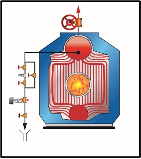
Boiler Water Chemistry Control: Preventive vs. Reactive Maintenance
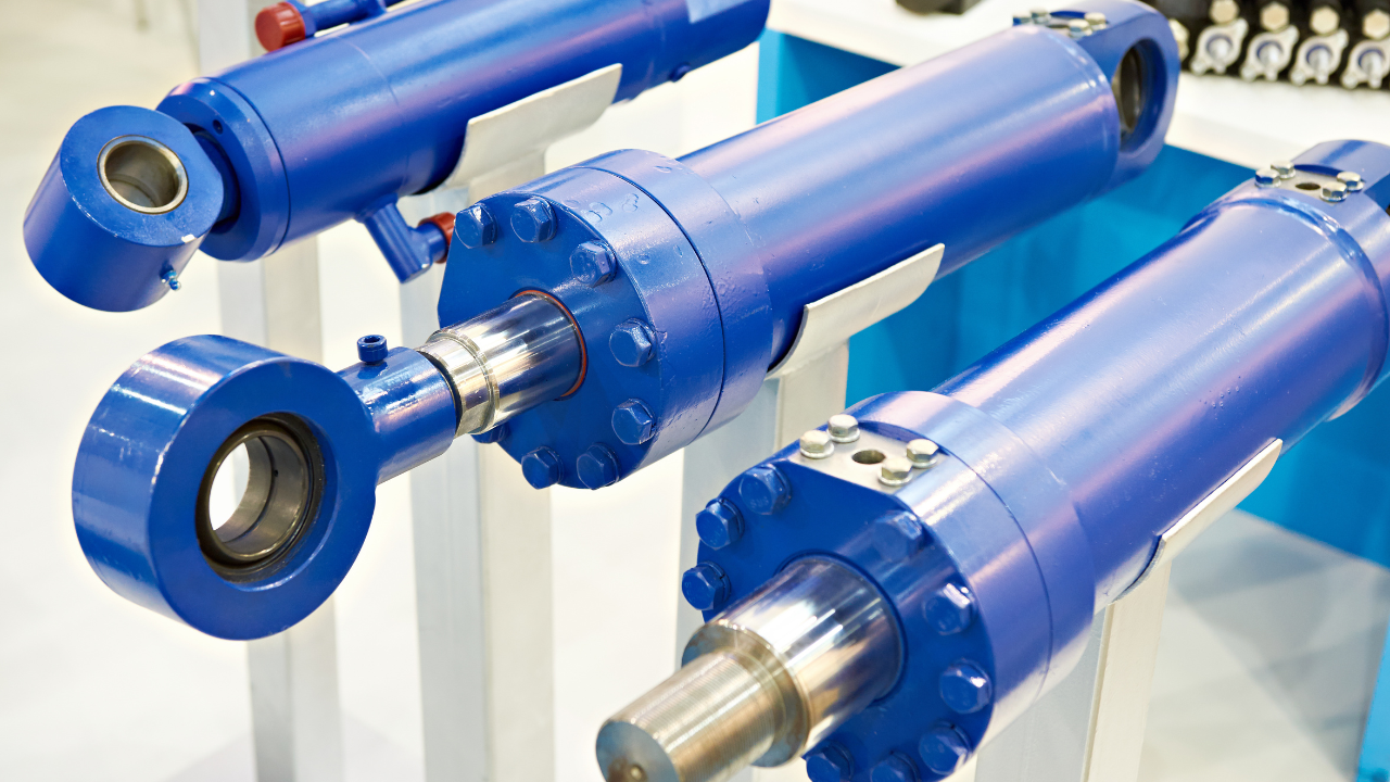
Proactive Maintenance for Hydraulic Cylinders

Preventive vs. Reactive Maintenance: Don’t Neglect Makeup Water and Condensate Return Treatment