How do I Test Relays and Contactors?
Greg Mecomber, Consultant, IDCON INC
Posted 02/16/2023
What are Relays and Contactors?
I often hear the words “relays” and “contactors” used seemingly interchangeably, but there must be a technical difference, right? So, I took a quick trip to Rexel Automation Solutions in Salisbury, MD to meet with Nate Titus, Account Manager, and get the skinny on these beloved but sometimes pesky industrial workhorses.
Relays and contactors effectively serve the same purpose by acting as a switch controlled by a control circuit, but what is the difference between the two?
Grabbing an Allen Bradley 100-C series contactor off the store, Nate points to a set of terminals on the top of the contactor. “One key difference between a contactor and a relay is that contactors are designed to be used with higher amperage 3-phase wiring while relays, on the other hand, are only intended to be used with single phase.”
“So, price isn’t the only difference between the two,” Nate continued with a charitable chuckle. “While it is true that there is often a price difference between the two of at least $100, the reason for this is the safety features that are built into the contactors that you will not find in a typical relay.” “Such as?” I ask. “Well, there are different features on different models, but all contactors will typically contain a set of overloads that will trip if the current travelling through the contactor exceeds the overload rating, thus providing an extra line of protection for your equipment.”
Nate went on to explain that relays are made up of four major parts: the coil, the armature, the contacts, and the terminals. Contactors are made up of these same parts PLUS overload protection and often auxiliary contact terminals connected to the low voltage circuit commonly used to power an indicator light, for example.
Want to know more about relays and learn about designing safety circuits? Click here.
Let’s Break Down the Anatomy
The coil is essentially an electromagnet made up of a simple coil of wire which has an electrical current passing through it, but its magnetic forces are not active all the time. In most cases, a low voltage current of 24 VDC is used to activate the magnet whenever a load such as an HVAC unit, motor, pump, etc. needs to be turned on or off. Think of it as the finger flipping a light switch.
If the coil functions as a figurative finger to the light switch, the armature acts like the toggle on the light switch itself. The electromagnetic force created by the coil pulls against the armature with enough force to cause it to move towards the coil and create an open between one set of contacts and close the circuit between another.
The contacts are the points at which a higher voltage current, often 120 or 240 VDC, passes through to power a process or component. Continuing with our light switch analogy, the contacts would be the inner contact surfaces within the light switch itself. Additionally, the terminals on the relay are the points at which the relay is connected to wire conductors to ultimately connect the power source to the intended load (such as the wires running through the walls from the light switch to the light socket).
Common Ways Relays Fail and What That Means for You
Arcing is an unavoidable characteristic of sorts when it comes to many electromechanical components such as relays. As the armature closes, the current will jump from one contact surface to another like a jolt of static electricity when the contact gap closes enough to allow it. This arcing is often not noticeable and does not truly pose any concern, but over time, pitting of the contact surfaces will occur due to this continued arcing. Consequently, the contact surfaces will corrode much faster if the relay is actuated at a high frequency.
This pitting results in a poor contact and an increased resistance between the contact surfaces which will diminish the quality of current that is supplied to the load.
Voltage spikes can occur in both the low voltage and higher voltage current paths. If there is a high enough or frequent enough spike on the low voltage path, the contacts can become damaged. If the spike occurs on the higher voltage path, the coil can either weld into practically one solid conductor or it can cause the wire that makes up the coil to break and no longer allow current to pass through. Both of these instances will result in the loss of inductance and therefore electromagnetism of the coil.
How do we Test for These Failures?
Safety: First, let’s get this out of the way. All electrical work must be performed by a qualified technician. Failure to follow OSHA safety standards may result in personal injury or death, fire hazard or equipment damage and may void the manufacturer’s warranty.
For more information on troubleshooting, check out this article.
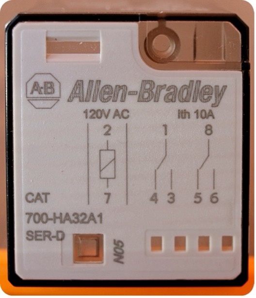
You’ll need to have access to a diagram of the relay contacts (often printed on the side of the relay and if not, it will typically be on a data sheet contained with the relay in its package) and an ohmmeter.

- Use the diagram to identify the terminals connecting to the relay coil generally represented by a symbol like the one above.
- With the relay de-energized and disconnected from the power source, touch the two ohmmeter leads to the two coil terminals. An Ohm reading for a good coil will vary, but it should be neither 0 Ohms nor OL as these indicate a damaged coil, and the relay will need to be replaced.
- Use the diagram to identify the terminals connecting to the normally open and normally closed contacts.
- Touch the two ohmmeter leads to terminals 1 and 3.
- While sustaining contact to the terminals, manually actuate the armature and observe the Ohm reading. While in the normally open position, the reading should be OL; while in the actuated or simulated energized state, which would result in a closed contact, the Ohm reading should be very low. If there is too much resistance between the two contact surfaces, this may indicate that the contacts have corroded, and the relay needs to be replaced.
Want to streamline your electrical troubleshooting? Click here to learn how to get it done in 7 steps.
Don’t miss IDCON’s upcoming Troubleshooting Course (still in development!) For an example of what will be included, watch the YouTube video above where Greg shows you have to troubleshoot a faulty relay.
Check out idcon.com for other training events coming up.

Related Articles
Safety Circuits, Force Guided Relays vs. General Purpose Relays

Understanding Shaft Alignment: Basics
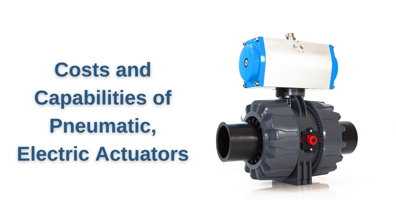
Costs and Capabilities of Pneumatic, Electric Actuators