Hydraulic System FMEA Made Easy
Paul Craven
In the not too distant past, most senior level managers would cringe when someone said a failure mode and effects analysis (FMEA) needed to be performed on the hydraulic system. What immediately came to mind is a bunch of highly paid people sitting around a table dreaming up ways to eliminate things that may or may not happen to their hydraulically operated equipment.
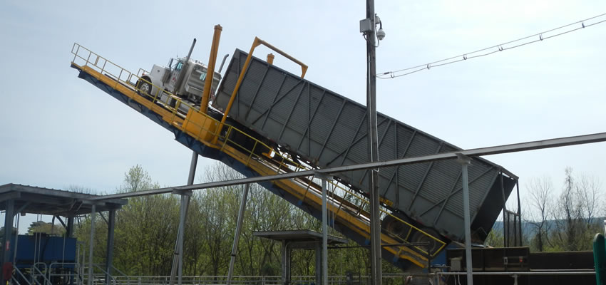
Figure 1: Truck dumper in operation (Courtesy of BRUKS)
What they finally realized is that the majority of their day-to-day work orders were being generated to repair things that were happening at the failure mode level, which was determined to be reactive maintenance. How times have changed! These days, the majority of those senior level managers have been promoted into positions within the reliability group and their technicians are now using improvement-based maintenance techniques. They have never looked back since!
One easy, yet effective way, to perform a FMEA on a typical hydraulic system is through gathering, analyzing and trending relevant data from a few properly placed inexpensive devices.
Failure Mode and Effects Analysis Defined
FMEA is a proven process, created within a spreadsheet, to help facility managers anticipate what might go wrong with a machine set or process and how that asset would fail to perform its intended function. FMEA also helps find the possible causes of functional failures and failure modes, and the likelihood of those being detected before occurrence. It requires a well-defined function statement that clearly describes the machine function or what it should do and performance or how it should do it, and must be quantitative or measurable.
Fundamentals of Hydraulics
In any hydraulic system, whether it’s a truck dumper in a paper mill or a farm tractor, there are only three things you need to know when determining how to identify functional failures and failure modes for a FMEA. They are the rate of flow vs. the required rate of flow, the direction of the flow vs. the required direction of flow and the operating pressure vs. the required operating pressure. Properly placing simple, inexpensive detection devices, such as flow meters and pressure gauges, in the design phase of your hydraulic system allows you to design in reliability and longevity of service. Breaking into a hydraulic system to add these devices after the fact is very costly and will introduce other unforeseen problems.
Getting Started
The following is an acceptable function statement developed by Drew Certain, P.E. Sales Engineer at Phelps Industries. They are the original equipment manufacturer (OEM) of the hydraulic truck dumper used to describe the FMEA process in the rest of this article.
Figure 1 shows a truck dumper in operation. The truck drives onto a deck and the entire truck is lifted into the air until it reaches the proper angle and the trailer has been emptied of its contents.
Truck Dumper Function Statement
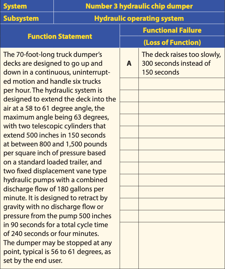
The 70-foot-long truck dumper’s decks are designed to go up and down in a continuous, uninterrupted motion and handle six trucks per hour. The hydraulic system is designed to extend the deck into the air at a 58 to 61 degree angle, the maximum angle being 63 degrees, with two telescopic cylinders that extend 500 inches in 150 seconds at between 800 and 1,500 pounds per square inch of pressure based on a standard loaded trailer, and two fixed displacement vane type hydraulic pumps with a combined discharge flow of 180 gallons per minute. It is designed to retract by gravity with no discharge flow or pressure from the pump 500 inches in 90 seconds for a total cycle time of 240 seconds or four minutes. The dumper may be stopped at any point, typical is 56 to 61 degrees, as set by the end user.
(Author’s Note: There also could be a dwell time at any point during the lift based on the operator, but for the purpose of this article, 240 seconds is being used.)
Now that is a function statement! It clearly describes what the truck dumper is supposed to do and how it should do it. The statement presents many things that can be measured.
Here is an example of a very poor function statement:
To unload as many trucks as we can.
What It Looks Like on Paper
The truck dumper function statement states that the 70-foot-long deck is designed to extend 500 inches in 150 seconds, with two fixed displacement vane type hydraulic pumps with a combined discharge flow of 180 gallons per minute.
A functional failure would be the deck extending too slow at 300 seconds, which is double the amount of time it is supposed to extend. This indicates that half the flow has been lost because in hydraulics, the rate flow is equivalent to the rate of speed. More flow equals more speed and less flow equals less speed for a given actuator’s size.
So, now it’s necessary to populate the document with the appropriate information:
- Function statement;
- Functional failure;
- Failure modes;
- Level 1 or the due to;
- Failure effects;
- Failure consequences;
- Appropriate task and detection device to mitigate the occurrence.
Your system is now identified: the Number 3 hydraulic chip dumper, your subsystem, the hydraulic operating system, your function statement and your first functional failure, which is “the deck raises too slowly.”
Figure 2 shows a clear function statement and describes in detail the scenario when the deck raises too slowly at 300 seconds instead of the required 150 seconds as a functional failure.
Next, determine the possible causes or failure modes that would allow this to happen.
One major failure mode: Ninety gallons or the full volume of one pump is lost, proving that amount of flow. This shows flow does equal speed.
What are at least 3 items that could have contributed to the failure?
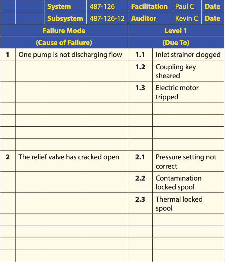
- The inlet strainer could be clogged, effectively choking off the inlet flow from the reservoir to the pump inlet.
- The key in the pump shaft coupling could be sheared, allowing the coupling to spin and the pump shaft not to rotate.
- The electric motor could have tripped, not allowing the electric motor shaft or the pump shaft to turn.
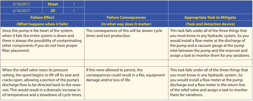
Here is the really great thing about a flow meter located in both the pump discharge line and the return line of the relief valve: you are able to immediately identify where the oil is going and where it is not going. Simply meaning, if the pump discharge flow meter shows zero flow, then the problem is the pump and does not go beyond that point.
Figure 3 shows two possible failure modes and three Level 1 due to reasons.
What are the failure effects, the failure consequences and the appropriate tasks to control these failures?
Figure 4 shows the failure effects, the failure consequences and the appropriate task to control them, as well as the devices to measure and trend the data to look for even the slightest variations in operating parameters.
Some people will keep drilling down and add problems with contamination or temperature. You can add devices to monitor these problems just to give you a warm and fuzzy feeling, BUT if you design your hydraulic system correctly, seal the unit, properly size and place your filters and keep the hydraulic oil clean, cool and dry, you will not have these problems. These are by-products of an improperly designed, improperly installed, improperly operated, or improperly maintained hydraulic equipment down to the component level.
High-Risk Failure Modes
You want to make sure to identify and address your high-risk failure modes. Small abrasions in the fluid conductor cause skin penetration, burn injuries and eye loss. Allowing the oil to atomize and become explosive can cause equipment damage and even loss of life. A relief valve that is set incorrectly and forced open would allow the oil to reach extreme temperatures, causing a 200°F to 280°F fire, resulting, again, in equipment damage and/or loss of life.
Inspection Frequency
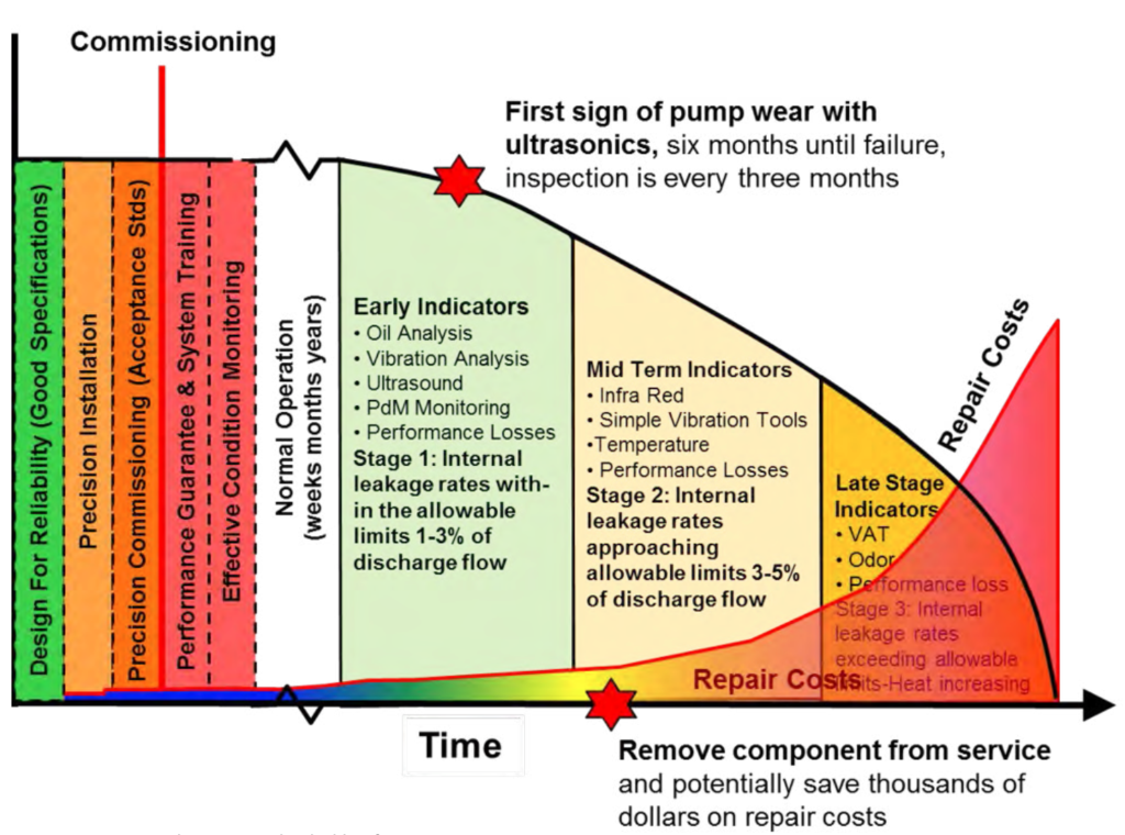
Many people have no idea that they DO NOT need to inspect their equipment on a weekly basis. Inspection frequency has nothing to do with age, time in service or expected life. The inspection frequency should be set by how much time there is between when the equipment can be first identified as potentially failing until it functionally fails. This could change based on the technology being used and the rate of change in the reading.
For example, the inspection frequency of the hydraulic pump should be at least one half the time between the ability to first detect the potential failure (P) and the functional failure (F).
Remember, the technology drives the frequency. If the time between P-F is six months, then the inspection frequency would be every three months. The key is to stay on top of the new detection technologies. This will allow you to determine when to remove the component from service, potentially saving your facility thousands of dollars in repair costs and thus increasing profitability.
Figure 5 is a customized P-F curve that shows that several things have to happen prior to commissioning a hydraulic system. It also shows early, midterm and late term indicators and when to remove a failing component from service.
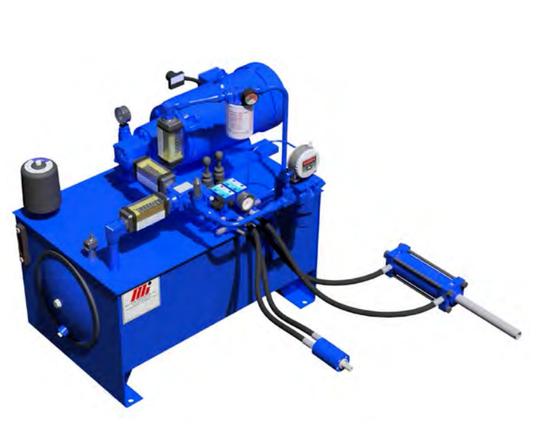
Okay, so here is the REAL spoiler. The following list identifies EVERY detection device you would ever need to detect and eliminate problems on ANY hydraulic system.
- Flow meters
- Gauges, pressure, vacuum and bypass
- Amp meter
- Heavy-duty breather to stop particle ingression (minimum) or you could use a bladder and totally seal the unit and recycle the air in the head space (preferred)
- In-line particle counter
- Test points for oil sampling and bleeding trapped air
- Temperature and level indicator
Put them in the proper place, as shown in Figure 6, and go work on your mechanical and electrical problems.
Conclusion
Conducting a FMEA on a hydraulic system doesn’t have to be complicated. All of the problems will always point back to three things: flow, direction of flow and operating pressure. This information allows you to eliminate the majority of problems your facility is experiencing at the failure mode level, even including the lower levels or the due to ones.

Paul Craven
Paul Craven, CFPHS, manages one of Motion Industries’ Repair Shops. He is certified by the International Fluid Power Society as a fluid power hydraulic specialist and has worked in the field for over 25 years. Visit the company’s newest Knowledge Site, Mi Fluid Power Specialist.
Related Articles

The Impact of Bearing Isolators on Life-Cycle Cost in Rotating Equipment
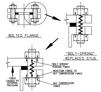
Prevent Flange Leaks with Proper Bolting Practices

Maintenance Apps for Smartphones

Digging Up Savings: Go with the Flow
Maintenance Theory: How do Motors Work?

Pumps: You Get What You Pay For... Or Do You?