Setting Techniques for Tapered Roller Bearings
David Novak, Timken
Introduction
Tapered roller bearings can be set at initial machine assembly to any desired axial or radial clearance. This unique feature enables a designer to control bearings to meet anticipated application operating conditions, and thereby provide optimum bearing and system performance.
Some advantages of tapered roller bearings pertaining to setting include:
- Longer bearing life, achieved by optimizing bearing settings while meeting application performance requirements
- Increased mounting stiffness, achieved by properly set tapered roller bearings resulting, for example, in better gear contact and longer gear life
- Easier assembly because cone and cup are separable
- The bearings can be set at the time of machine assembly, allowing wider shaft and housing tolerances
The setting of tapered roller bearings can be readily accomplished by a wide variety of viable methods. These bearings can be set manually, supplied as pre-set assemblies, or set by automated techniques. There are a number of approaches, considerations and advantages for each, with special focus on five popular automated techniques, i.e. — set-right; acroset; projecta-set; torque-set; and clamp-set (Table 1).
Bearing Setting
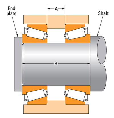
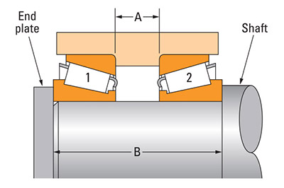
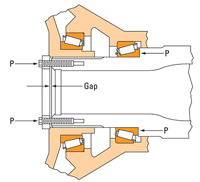
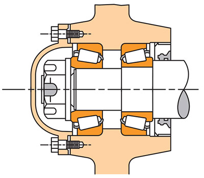
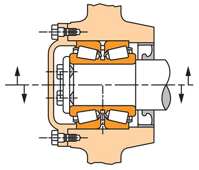
With tapered roller bearings, the term “setting” simply indicates the specific amount of end-play (axial clearance) or pre-load (axial interference) within a mounted bearing. The flexibility to easily adjust and optimize setting at the time of assembly is an inherent advantage of tapered roller bearings. Unlike other types of anti-friction bearings, tapered roller bearings do not require tight control of shaft or housing fits to obtain setting. Because tapered roller bearings are mounted in pairs (Fig. 1), their setting is primarily dependent upon the axial location of one bearing row relative to the opposite row.
The three primary conditions of bearing setting are defined as:
- End-play. Axial clearance between rollers and races producing a measurable axial shaft movement when a small axial force is applied — first in one direction and then in the other — while oscillating or rotating the shaft (the reference bearing load zone less than 180°).
- Pre-load. Axial interference between rollers and races such that there is no discernible axial shaft movement when measured as described above. A rolling resistance to shaft rotation results, which may be measured (load zone greater than 180°).
- Line-to-line. A zero setting condition; the transitional point between end-play and pre-load.
A bearing setting obtained during initial assembly and adjustment is the “cold” or “ambient” bearing setting, and is established before the equipment is subjected to service.
Bearing setting during operation is known as the “operating bearing setting,” and is a result of changes in the ambient environment bearing setting due to thermal expansion and deflections encountered during service. The ambient bearing setting necessary to produce the optimum operating bearing setting varies with the application. Application experience, or testing, generally leads to the determination of optimum settings. Frequently, however, the exact relationship of ambient to operating bearing settings is unknown, and an educated estimate has to be made. To determine a suggested ambient bearing setting for a specific application, contact your bearing representative.
Generally, the ideal operating bearing setting is near-zero, to maximize bearing life. Most bearings are set with a cold setting of end-play at assembly. This comes as close as possible to the desired near-zero setting when the unit reaches its stabilized operating temperature.
Some applications are set with cold pre-load to increase rigidity and axial positioning of highly stressed parts that would otherwise be dramatically affected by excessive deflection and misalignment.
Excessive operating pre-load must be avoided, as bearing fatigue life can be drastically reduced. Also, excessive operating pre-load can lead to lubrication problems and premature bearing damage due to high heat generation.
Load zone is a physical measure of the raceway-loaded arc and is a direct indication of how many rollers share the applied load. For a single-row tapered roller bearing, maximum life is obtained with a load zone of approximately 225°.
Figure 2 shows the graphical representation of bearing L10 life vs. the operating bearing setting for a typical (overhung) pinion bearing mounting.
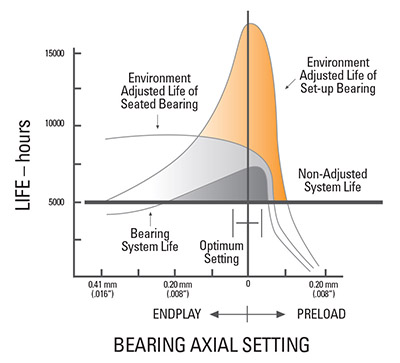
The ideal operating setting that will maximize bearing system life is generally near-zero to slight pre-load.
Manual Bearing Setting
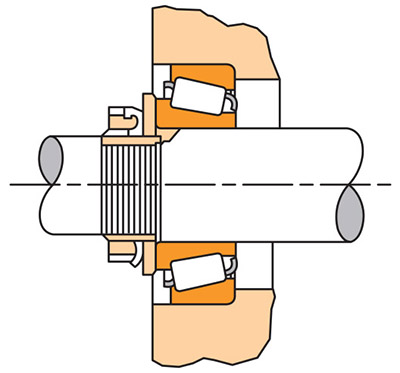
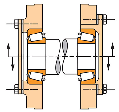
Manual methods are frequently used to set bearings on a variety of equipment with low-to-moderate volume production requirements, whereby a less-than-exact, primarily end-play setting range variation is acceptable. No special tooling, gauges, charts or fixtures are typically required, but assembler skill and judgment are necessary. For example, in the case of a conventional truck non-driven wheel with a single adjusting nut design (Fig. 3), manual setting involves tightening the adjusting nut while rotating the wheel until a slight bind is felt. Then the adjusting nut is backed off 1⁄6-to-1⁄4 turn to the nearest locking hole — or sufficiently to allow the wheel to rotate freely with some minimal end-play. The adjusting nut is then locked in this position. Skill and judgment are required to determine when the wheel binds slightly in rotation. The more complicated the equipment, and the bulkier and heavier it is, so is a greater degree of skill and judgment required.
For certain complex designs, large equipment, or highproduction applications, manual setting may be too troublesome, of inappropriate accuracy and reliability, or too time consuming. The Timken Company has devised pre-set bearing assemblies and automated setting techniques as alternatives to manual setting.
Pre-set Bearing Assemblies
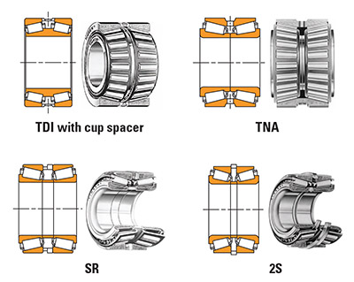
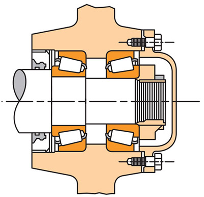
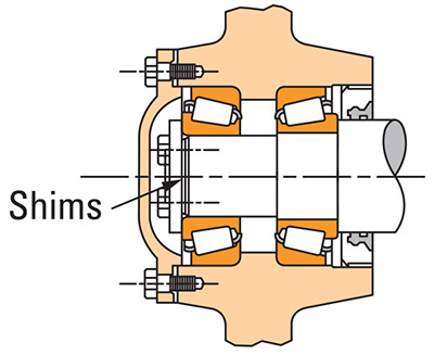
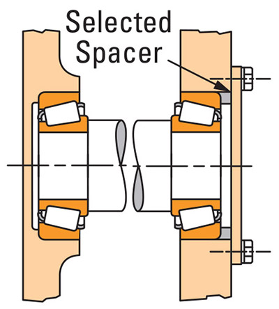
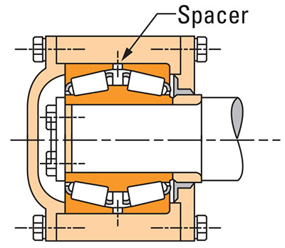
Many applications utilize or require the use of two-row or close-coupled bearing assemblies. This will depend upon the design and operating characteristics of the machine (e.g., thermal growth effects, high loads, etc.). To facilitate bearing settings of this type of design, pre-set bearing assemblies are frequently used. Pre-set bearing assemblies are available in a variety of forms, styles and arrangements, but for the most part are typically referred to as spacer bearings (Fig. 4). The majority of pre-set bearings are manufactured and supplied with spacer rings “custom-fitted” between the bearing rows to control the internal clearances (Ref. “2S”- and “TDI”- types). As such, these customized or “matched” spacers cannot be interchanged with any other bearing assembly. Other pre-set assemblies such as “SR”- or “TNA”-types may apply interchangeable spacers and/or bearing components. Such interchangeable assembly components are designed to hold closer control of the critical tolerances that affect bearing setting; as a result, they can be randomly selected.
Each pre-set bearing is supplied from the manufacturer with a specified (unmounted) internal clearance or bench end-play (BEP). This BEP is chosen to provide the desired mounted setting range for the given application requirements. The mounted bearing setting range is determined from this BEP, based strictly on the effect of shaft and housing fits. Typically only one tight-fitted (shaft or housing) requirement is applied (i.e., on rotating member). This results in expected mounted setting ranges of less than 0.008″. The mounted setting range of interchangeable component assemblies is typically wider than that for “matched” spacer assemblies. To apply pre-set assemblies in an application, simply mount and ensure proper clamping of the bearing components through the spacers.
Typical Pre-Set Bearing Assembly Applications
Pre-set bearing assemblies are widely and frequently used in many industrial applications. Typically this includes application in: planet pinions; hitch or linkage positions; transmission idler gears; fan hub shafts; water pump and idler pulley shafts; sheaves; conveyor idlers; winch drums, at the fixed and float positions of mining equipment; propel and swing drives; and in larger gear box drives.
Automated Bearing Setting Techniques
In addition to pre-set bearing assemblies, Timken has developed five popular automated bearing setting techniques (set-right; acro-set; projecta-set; torque-set; and clamp-set) as alternatives to manual adjustment.
Table 1 provides a matrix format of various features of these techniques. Each method’s ability to hold a reasonably controlled mounted bearing setting “range” is compared on the first line of this table. These values are simply an indication of overall variability in setting for each method and have nothing to do with the “pre-load” or “end-play” setting target. For example, under the set-right column the expected (probable or 6-sigma) setting variation — due to control of certain bearing and housing/shaft tolerances — could range from a typical minimum of 0.008″–0.014″. This range of setting can then be apportioned between end-play and pre-load to best optimize the bearing/application performance.
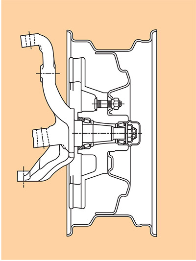
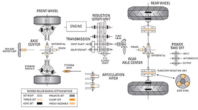
Figure 5 utilizes a typical four-wheel-drive farm tractor design to demonstrate examples of the common application of tapered roller bearing setting methods.
The specific definition, theory and formal process for the application of each technique is discussed in detail in the following sections.
Set-Right
Set-right eliminates manual setting adjustment of tapered roller bearings by controlling certain bearing and mounting system tolerances. The statistical laws of probability are applied to predict the effect of these tolerances on the bearing setting. Generally, the set-right method requires closer control of some shaft/housing machining tolerances, as well as closer control (with special class and code) of critical bearing tolerances.
The method considers that each component involved in the final assembly of a machine has a controllable tolerance range for critical dimensions. The laws of probability indicate that combinations of all low tolerances or all high tolerances will rarely occur in such an assembly. It then follows that for a “normal tolerance distribution” (Fig. 6), the overall dimensional stack-up of all parts will statistically tend to be somewhere in the middle of the total possible tolerance range.
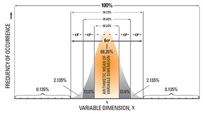
The goal of the set-right method is to control only the most critical tolerances affecting bearing setting. These tolerances may be completely contained within the bearing or may involve certain mounting components (i.e., widths A and B of Fig. 1 or 7, plus shaft OD and housing ID). The result is an acceptable bearing setting that will occur within a desired range, with a defined statistical probability/reliability for all assemblies. (A probable reliability of 99.73% or 6-sigma is typical, but in higher-volume production a 99.994%, or 8-sigma reliability, is sometimes required). There are no adjustment steps required to use the set-right concept; the components of the machine are simply assembled and clamped.
All dimensions affecting the bearing setting in a machine assembly — such as certain bearing tolerances, shaft OD, shaft length, housing lengths, and housing bores — are considered as independent variables when calculating the probable range. In Figure 7 both cones and cups are mounted with conventional tight fits and the end-plate is simply clamped against the end of the shaft.
Special set-right considerations:
- The overall calculated bearing setting range can vary significantly, depending on the bearing K-factor, its equivalent axial tolerance, and the number of tight-fitted components applied (i.e., larger with both tight cones and cups). A review of the application during the design stage will enable selection of special tolerance-controlled bearings and assist in optimizing the mounting design for the smallest probable setting range.
- To control bearing mounting dimensions, the tolerances of the bearing system mounting dimensions used in establishing the probable setting range must be consistently maintained and, in some cases, more tightly controlled.
- If the probable bearing setting range cannot be tolerated by the application, and attempts to reduce the larger tolerances are not practical or successful, then consider the spin-right variation to set-right.
- The same class and code of bearing must be used for field service replacement as was used for the initial production.
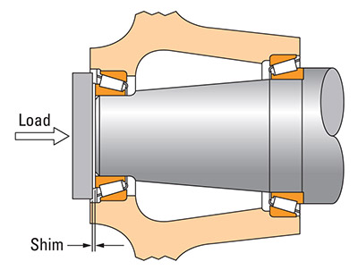
Spin-right variation of the set-right technique. In some cases the probable bearing setting range with set-right can be too large for the application. To reduce this range and still apply the laws of probability, a technique called spinright is used. This technique can be applied to applications that could also lend themselves to “shim-pack” adjustment (Fig. 16). To apply this method, the existing probable range is simply divided by a factor of two or three, depending on which is necessary to result in an acceptable setting range for the application.
For example, assume the probable bearing setting range for the design in Figure 1 is calculated to be 0.018″ and the application demands a setting of 0.000″ – 0.009″ end-play. The current range must be divided by a factor of two. Thus with spin-right the desired shim increment (apply shim between endplate and shaft) would be equal to 0.009″ and the following technique applied:
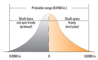
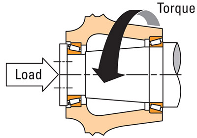
- Assemble the gearbox without a shim and “spin check” — without the seal in place — to determine if the bearings are set with end-play or pre-load. Under the first spin check, if the shaft spins freely, end-play is present (Fig. 8) and the bearings are properly set.
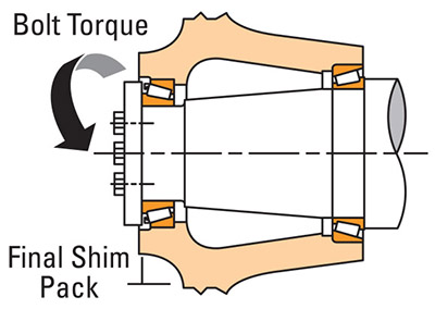
- If the shaft does not spin freely, the bearings are preloaded. Then a 0.009″ shim must be installed. A second “spin check” should result in a freely rotating assembly indicative of end-play.
- If pre-load is the desired setting, the spin-right procedure would be applied in reverse of the above example: if the shaft rotates freely, the bearings are not properly set and a shim of 0.009″ would need to be removed.
Typical set-right applications. The set-right technique has been used for a wide variety of bearing setting applications, which include: tractor PTO assemblies — especially with blind end or split housing designs; automotive front-drive wheels; gear reducer shafts; planet pinions; and sprockets and torque hub units, as used on construction and mining equipment.
Acro-Set
This widely used setting technique is based on Hooke’s law, which states: within the elastic material limit, component deflections are proportional to the load applied (i.e. F = kx, where k = system spring rate). This method assumes that total system deflection of an assembly will be consistent and repeatable for a given applied load (Fig. 9) in an application where parts and sections of parts are reasonably uniform throughout a group of units.
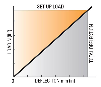
To establish the method for a given machine configuration, a dimensional reference condition known as the “deflection constant” must first be determined. The deflection constant is simply the (averaged) system deflection, resulting from a known “set-up” load applied through the bearings, as determined from the testing of several preproduction units. This system deflection is typically gauged by measuring a shim gap (Fig. 10).
The acro-set system constant is then developed; it equals the deflection constant for a given applied “set-up” load, plus the desired bearing setting. In production this constant is added to the measured shim gap to determine the final shim pack thickness for each unit.
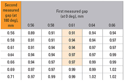
The selection of the final shim pack thickness for each unit is simplified by use of a shim chart (Fig. 11). The shim pack thickness indicated on the chart includes the effect of the previously established acro-set constant. Note that the shim chart facilitates proper shim pack determination based on shim gap measurements taken at two positions, 180° apart. The planetary drive wheel assembly (Fig. 10) will be used to illustrate the acro-set technique.
- The “set-up” load “P” was established by pretesting and is applied by 2 cap-screws (180° apart). The applied load is proportional to the bolt torque. (Commonly, a much larger “seating” force is first applied and the bearings rotated to ensure proper assembled positioning of the components prior to the acro-set shim gap measurement.)
- Rotate or oscillate the bearings while applying the “set-up” load “P” and measure the shim gap — first at 0° and again at 180°.
- Select the proper shim pack thickness (from the shim chart), equal to the measured gap plus the predetermined acro-set system constant (that was established from pretested assemblies). The Figure 10 chart averages the two readings and provides the final shim pack thickness. In this case, 0.66 at 180° and 0.61 at 0° gives a 0.97-thick shim pack.
- Install the final shim pack and torque up all cap-screws to their clamp-up torque.
Special acro-set considerations:
- Bearing “seating” and “set-up” loading is typically applied with multiple cap-screws (i.e. Load = NT/(dμ) where: N = # of cap-screws, T = cap-screw torque, d = cap-screw diameter, and μ = coefficient of thread friction; where typical μ = 0.17). Commonly, the applied seating force should be 2–3× Ca (90) and the applied set-up force chosen as ¾–1× Ca (90) of the lowest capacity bearing in the system.
- Loose-fitted adjustable component; a loose-fitted member at the adjustable position is preferred. However, variations to tight-fitted cups and cones can be made as described below:
- The use of tight cups in carriers that are loose fitted in the housing.
- The use of a loose fitted “master” cup or cone for the bearing setting operation (mean fit compensated for in acro-set constant).
- Fixture designs with built-in compensation for the tight fitted member (projecta-set).
- All components essential to the acro-set concept, such as housing walls and cover plates, must have a fairly uniform section size in successive production units.
- The design must lend itself to applying a set-up load to the movable bearing race for adjustment.
- The bearings must be rotated or oscillated while applying the set-up load.
- The design must also lend itself to gap measurement of the movable member.
- The thickness of the actual shim pack used should be verified.
It may be seen from this simplified schematic that projectaset is basically a method of ‘projecting’ the two faces essential to measuring the spacer size from an otherwise inaccessible position to a point where gauging is possible.
- The tapered roller bearing assembly with lower cone pressed into position on the shaft
- Also lower and upper cups in the housing but without upper cone
- Spacing element projects lower cone abutment face a known distance (x) (clear of shaft end)
- Gauging element projects upper cup track the same distance (x)
- Upper cone in gauging position
- Gauging point (e.g. for low volume, a dial indicator, or for high volume, an electronic transformer – LVDT) arranged and pre-set to indicate spacer size (S)
In this schematic, a movable base (H) is shown which, by the application of a known force, seats the upper cone in its ‘projected’ track, i.e. — the gauging element then giving a direct reading of the necessary spacer size. In practice, alternative methods may be used to suit any particular production facilities and requirements; (for instance, a static base with the gauging load applied by a moving head from the top).
Typical acro-set applications. Examples where the acroset method has been successfully applied to tapered roller bearings include: manual transaxles; drop box transmissions; farm tractor axle assemblies; power take-off units; planetary pinions; differential and pinion shafts; gear reducers; and off-highway truck and tractor wheels.
Project-Set
The projecta-set technique is similar in concept and application to acro-set, but adds additional versatility and sophistication through utilization of a special gauging fixture. This gauge enables one to “project” an inaccessible shim, spacer gap, or reference surface, to a position where it can be easily measured. This gauge typically incorporates the use of a dial indicator or an LVDT for measured readings. It is also readily applied in designs where the adjusting component (cone or cup) is tight-fitted without sacrificing assembly speed or accuracy. The method (Fig. 12) consists of two key gauging elements: a spacer sleeve (Ref. C) and a tapered gauging sleeve (Ref. D), of known (typically equal) design lengths (Ref. X). These sleeves will project the inaccessible spacer gap beyond the shaft end.
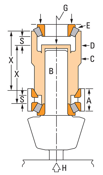
To illustrate the projecta-set method, reference a typical spiral bevel pinion shaft assembly (Fig. 13). In this indirect- mounted, cone-adjusted design the bearing setting is achieved through the use of a spacer located between the two cone front faces. The cups and cones are tight-fitted in this application; the required gauging steps are:
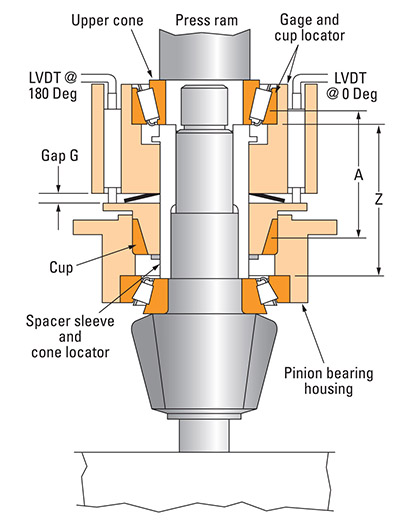
- Place the assembled pinion shaft, except for the upper cone and spacer, on the press table. Position the gauge onto the upper bearing cup and apply the upper bearing cone (Fig. 13).
- Activate the press to clamp the gauge through the two bearing cones. A known axial load is applied through the bearing cups at this time by the Belleville spring internal to the gauge. (Note that the press is required simply to clamp the upper cone in place, against the spacer sleeve, for proper seating; some gauge designs accomplish this with a threaded nut design.)
- Oscillate the gauge (handles) to seat the bearing rollers. The LVDT probes then measure the axial displacement between the two gauging members and the required spacer size is displayed on the digital readout.
- The spacer size is determined by the gauge based on the formula (Fig. 13): S = Z − A + K
Where
S = Spacer size required
Z = Sleeve length (fixed)
A = Variable distance between corresponding diameters on the tapers of cone and cup locator (“zeroed” dimension is known)
K = Constant to compensate for system deflection due to gauge spring load, mean tight cone fit effect (loss of clearance), and the desired bearing setting
G = Measured gap, which represents the change in distance “A”; distance “A” includes “G”
Special projecta-set considerations:
- The size, weight, cost and design of the projecta-set gauge should be reviewed for specific application viability. Typical gauging cost for an industrial application, incorporating LVDT and internal gauge springs, is approximately $10,000 each. To increase set-up efficiency (for higher volumes over 30,000 assemblies/year), the designer should consider design/usage of a special automated press and press fixture to apply the gauge.
- Separate gauges or interchangeable components (i.e. dual tapers) would be required if various models or shafts of the same application use a different bearing series.
- An alternate method of field servicing would be required to set the tapered roller bearings (acro-set is similar and should be given primary consideration).
Advantages of projecta-set:
- Prevents time-consuming teardowns to change shims or spacers in an application with tight cone or cup fits.
- It can be readily applied to automated assembly processes.
- Human judgment is minimized when compared to past traditional manual methods.
- The use of projecta-set gauges requires minimum training time.
- The projecta-set method provides consistent and reliable settings.
Torque-Set
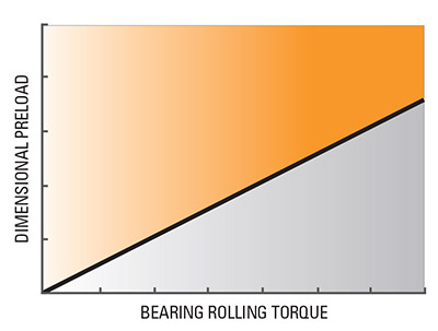
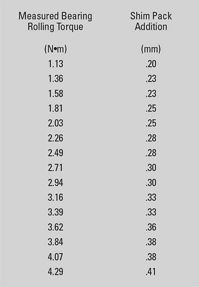
The torque-set method is based on the principle that the rolling torque in a pre-loaded bearing directly increases as a function of the applied pre-load force (typically measured by dimensional pre-load). Laboratory tests have shown that the torque variation of a new bearing is small enough to effectively use bearing rolling torque as a basis for predicting/ gauging a consistent dimensional pre-load setting. This relationship (Fig. 14) is established during pre-testing of several units and loads. Shims are added or subtracted after initial bearing rolling torque is measured to satisfy the desired bearing setting — either end-play or pre-load. A shim chart is normally used to assist selecting the final shim pack for each unit (Fig. 15).
The steps required to perform the torque-set technique are outlined below:
- Assemble the unit with a reference (constant thickness) shim pack that assures a pre-load in the system (Fig. 16). Note the resulting bearing pre-load will actually differ for each assembly, depending on the variations in the accumulated tolerances of the component parts.
- Measure the bearing rolling torque (Fig. 17).
- Select the final shim pack thickness based on the preconstructed shim chart (Fig. 15).
- Install final shim pack and complete the assembly by installing all cap screws (Fig. 18).
Bearing rolling torque is influenced by rotational speed and lubricant used. In any application using the torque-set approach, the lubricant and speed should remain constant.
The most common method of measuring bearing rolling torque is with a torque wrench. Sometimes a socket can be used, which fits over a nut on the end of the shaft or, if this is not possible, a special adapter can be made that fits the end of the shaft. In cases where the housing can be rotated, the torque wrench is adapted to the housing to measure rolling torque.
If a torque wrench cannot be used, a spring scale may be substituted to measure bearing rolling torque. Using a string wound around a gear or wheel and a scale, record the pull force needed to keep the assembly turning. Rolling torque is calculated by multiplying the radius of the gear or wheel around which the string has been wound by the pull force. This step could be avoided by a shim chart, which indicates pull force vs. shim pack size.
When measuring bearing rolling torque, turn the shaft as slowly as possible while maintaining smooth rotation.
Special Torque-Set considerations:
- Ability to measure rolling torque. The design must lend itself to measuring the rolling torque of the bearings. Where other components such as seals, piston rings, etc. contribute to the torque, provisions must be made to recognize and isolate these torque values from the bearing rolling torque. An example would be to record the drag torque of a shaft and seal in an end-play condition, then “add-on” the required bearing rolling torque for the preload condition.
- Ability to “reseat” tight-fitted members.When tight-fitted members are used for bearing adjustment, provisions must be made to “re-seat” or back-press that member after the torque-set load has been applied and the final shim pack determined.
- Bearing rolling torque is influenced by rotational speed and applied lubrication.These should be kept constant between units. The most common method of measuring rolling torque is with a torque wrench. When measuring rolling torque, turn the shaft as slowly as possible (estimated at 3.5 rpm) while maintaining smooth rotation.
- Torque-set.Should not be used if there is an unbalanced load (created, for example, by heavy parts, clutch plates or caliper brakes); this would cause the torque to vary during rotation.
- For field servicing,the torque-set method should not be used to reapply previously operated (e.g., run-in) bearings; a new set of bearings or alternate technique must be used.
Typical torque-set applications.Torque-set has been used successfully on various industrial and automotive applications. Typical applications include pinion and differential shafts, transmission shafts, and gearbox shafts.
Advantages of torque-set:
- Usually, no special fixtures or tooling are required; a torque wrench or simple spring scale and cord are all that are needed.
- No shim gap measurements are required; the shim pack is simply changed to obtain the correct setting.
- This method is useful in equipment where manual methods are physically impractical or difficult. However, it may not be practical in very large equipment.
- Torque-set can be applied to field servicing when new bearings are installed.
Mounting Designs and Setting Devices
Tapered roller bearings can be mounted in various configurations, and there are a variety of devices available to set the bearings to the desired end-play or pre-load in an application.
Cone-setting devices.In an indirect mounting, generally one cone is backed against a fixed shoulder while the other cone is movable and backed by some setting device.
A slotted nut (Fig. 20) can be used for obtaining the bearing setting. The nut is locked in place with a cotter pin. Both the nut and washer should be of sufficient size to give adequate backing to the cone. Two cotter pin holes in the shaft, spaced 90° apart, are used to obtain twice as many locking-positionsper- revolution of the nut, and a corresponding, closer bearing setting. A locknut, tongued washer, and lock-washer can be used instead of a slotted nut (Fig. 21). (See the Auxiliary Parts in the Tapered Roller Bearing Guide for other locknut arrangements.)
A stake nut (Fig. 22) can be used for setting the bearings; and peening the thin section into a keyway slot locks it in place.
The setting in Figure 23 is obtained with shims and an endplate held in place by cap screws in the end of the shaft. A slot may be provided in the end-plate to measure the shim gap.
A TDO-type bearing with cone spacer, above the centerline (Fig. 24) and a TNA-type bearing, below centerline, are manufactured with a fixed internal setting built into the bearing. The TDO-type bearing is shown assembled on the shaft with a cone spacer and clamped against a shoulder by an end-plate. The TNA-type bearing is assembled on the shaft with the cones butted together and similarly clamped against the shoulder. No further set-up provision is required in either case.
Cup-setting devices.In a direct mounting, generally one cup is backed against a fixed shoulder, with the movable cup positioned by some satisfactory setting device.
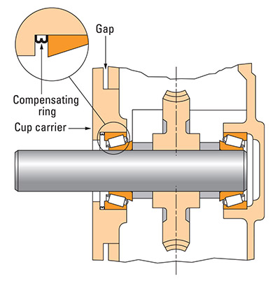
A cup carrier (Fig. 25, above centerline) and cup follower (below centerline) use shims for setting, and the carrier or follower is held in place by cap-screws.
Bearings can be set by the use of a selected cup spacer with the end-plate secured to the housing by cap-screws (Fig. 26).
A TDI-type bearing with a cup spacer (Fig. 27) is supplied with the cup spacer providing a specific, fixed internal setting. The bearing is clamped by a cup follower through the cups and spacer against the housing shoulder. No further setup provision is required.
Summary
The fact that tapered roller bearings can be set is an advantage over other types of bearings. Manual setting has been considered an acceptable approach by many manufacturers and will continue to be used. The trend, however, is toward automated bearing setting procedures because of cost and more exacting performance requirements.
The selection of an automated bearing setting technique is best made early in the design stage.
But, if the equipment is already designed and built, one or possibly a combination of setting techniques could be incorporated to improve setting reliability and reduce assembly time.
David Novak, david.novak@timken.com
Related Articles
Hydraulic Filters that Do More Harm than Good

The Importance of Minimizing Corrosion Product Transport to Steam Generators

Digging Up Savings: Go with the Flow

Pump Technology Balancing Tradition & Innovation

Electrical Corona & Testing

The Impact of Bearing Isolators on Life-Cycle Cost in Rotating Equipment