Protection of Equipment During Storage, Standby and Decommissioning
www.machinerylubrication.com
Maintaining spares and redundant machinery in a prime state, ready for operation, can be a daunting proposition, particularly given that most of the planet is covered with a substance that tends to attack these stored and standby machines. We call the substance water. It is vital to life, health, happiness and keeping the wheels turning in the wide world of manufacturing. Water also has the distinct potential to wreck idle industrial machines.
Machinery can be idle from intermittent use, stand-by (redundancy), storage for spare parts, or for temporary decommissioning. This article looks at practices that protect equipment characterized as decommissioned, short-term storage or storage of stand-by capacity.
Asset Preparation for Decommissioning
Preserving or inhibiting corrosion of inactive process machinery depends on the type of equipment, expected length of inactivity and the time required to restore the equipment to service.
Petrochemical companies usually develop their standards based on such criteria. One recent typical mothballing program for indefinite storage in a northern climate zone was planned and executed as follows and forms the basis for the author’s recommendations.
Centrifugal and Rotary Pumps
- Flush pumps and drain casing.
- Neutralize acid or caustic pumps.
- Fresh water flush and air-dry all cooling jackets.
- Fill pump casing with mineral oil containing five percent rust-preventive concentrate. (Specific products for rust preventives that can be used as vapor-phase inhibitors for wet systems include Cortec or similar products available from companies such as VpCI Technology.)
- Plug cooling water jackets – bearing and stuffing box – but keep low-point drain valve cracked open slightly.
- Coat space where shaft protrudes through bearing or stuffing box housings with Product 1 (see Table 1) or similar product and cover with tape.
- Coat all coupling parts except elastomers with Product 1.
- Coat all exposed machined surfaces with Product 1.
- Fill bearing housing with mineral oil containing five percent rust-preventive concentrate.
- Pumps do not require rotation.
- Close pump suction and discharge block valves.
Reciprocating Pumps
- Flush and drain pump casing.
- Neutralize if caustic or acid.
- Blind suction and discharge nozzles of pump
- Fill liquid end with mineral oil containing five percent rust-preventive concentrate. Bar piston over to coat all surfaces. Allow some space for thermal expansion.
- Fill steam end with mineral oil containing five percent rust-preventive concentrate. Bar piston to coat all surfaces.
- Close inlet and outlet valves.
- Coat all joints where shaft protrudes from casings with Product 1. Cover with tape.
- Coat exposed piston rod, shafts and machined parts with Product 1.
- Fill bearing housing and gearbox with mineral oil containing five percent rust-preventive concentrate.
- Fill packing lubricator with mineral oil containing five percent rust-preventive concentrate.
Turbines
- Isolate from steam system.
- Seal shaft openings with silicone rubber caulking (Sealastic® or equal – black to discourage pilfering) and tape.
- Dry out with air.
- Fill turbine casing with oil containing five percent rust-preventive concentrate including steam chest. Hold governor valve open as necessary to ensure chest is full. Vent casing, as required, to remove trapped air. Fill trip and throttle valve with oil.
- Install a valved pipe on casing which can serve as filler pipe for adding oil to fill casing.
- Allow space for thermal expansion of oil in pipe.
- Coat all external machined surfaces, cams, shafts, levers and valve stems with Product 1.
- Coat space between case and protrusion of shaft with Product 1. Cover space with tape.
- Fill bearing housing with oil.
- Coat casing bolts with Product 1.
Large Fans
- Coat coupling and all external machined surfaces with Product 1.
- Spray Product 2 on fan wheel.
- Crack open casing low-point drain valve.
Gearboxes
- Fill gearbox and piping with oil containing five percent Product 1.
- Plug all vents. Allow space for thermal expansion.
- Install a valved pipe on casing which can serve as filler pipe for adding oil to fill casing.
Large Motors
- Blank oil return line.
- Seal shaft openings with silicone rubber caulking and tape.
- Fill bearing housing with oil containing five percent rust-preventive concentrate.
- Install a valved standpipe such that the inlet is higher than the bearing housing.
- Coat all exposed machined parts with Product 1.
- Do not rotate motor.
Centrifugal Process Compressors
- Purge compressor casing of hydrocarbons.
- Flush internals with solvent to remove heavy polymers.
- Pressurize casing with nitrogen.
- Mix five percent rust-preventive concentrate to existing lube and seal oil. Circulate oil through the entire system for one hour.
- Blank oil return header.
- Seal shaft openings with silicone rubber caulking and tape.
- Fill bearing housing with oil containing five percent rust-preventive concentrate by running turbine-driven pump at reduced speed.
- Fill oil console with mineral oil containing five percent rust-preventive concentrate.
- Fill compressor with nitrogen when it is at ambient temperature. Turn off all heat tracers.
- Coat all exposed machined parts, including couplings, with Product 1.
Lube and Seal Oil System
- Add five percent rust-preventive concentrate to lube and seal oil.
- Circulate oil throughout piping system. Open and close control and bypass valves so that oil will reach and coat all piping and components. Circulate for one hour. Vent trapped air from all components and high points.
- Block in filters and coolers. Fill with oil containing five percent rust-preventive concentrate but allow small space for thermal expansion. The water side of coolers should be drained and air-dried. Plug all vents. Lock drain connections in slightly open position.
- Fill reservoir with oil containing five percent rust-preventive concentrate. Blind or plug all connections to tank including vent stack.
- Coat exposed shaft surfaces and couplings of oil pumps with Product 1.
Reciprocating Compressors
- Purge compressor cylinders of hydrocarbons.
- Blank compressor suction and discharge.
- Fill crankcase, cooling water jacket and valves with oil containing five percent rust-preventive concentrate. Install a valved standpipe. Allow space for thermal expansion.
- Coat all exposed machined parts with Product 1.
- Top-up oil level in the cooling water jacket.
Short-term Equipment Storage Strategy
The probability of equipment failure is high following commissioning of equipment, whether for initial operation or following rebuild. Machines can often sit at a new industrial site for months while the arduous process of site construction creeps along. Unless the buyer clearly specifies storage measures in the contract, it is likely that the machine would be shipped without provision for storage. Onsite storage preparation for the three to 12 months at a construction site is usually termed a preventive maintenance (PM) program. Storage protection plans would look like the following, again in a northern, dry climate:
Rotation
Rotate all motors, turbines, compressors, pumps (excluding deep well pumps with rubber bushings), fin fans, blowers, aerators, mixers and feeders every two weeks.
Visual Inspection
When rotating exposed machined surfaces, check shafts and couplings to see that a protective coating has been applied and has not been removed. Reapply if needed.
Check all lubricating lines to see if any tubing, piping, tank or sump covers have been removed. Retape ends and cover. If flanges are open on machinery, notify pipe fitter general foreman or other designated personnel.
Inspect the interior of lube oil consoles on a six-week schedule. Check to see if the reservoir is clean and rust- and condensate-free. Clean and dry if needed, then fog with rust-preventive concentrate.
Draining of Condensate
Drain condensation from all bearing housings, sumps and oil reservoirs on a once-per-month schedule. If an excessive amount of condensation is found, recheck once a week, or at two-week intervals depending on condensate present.
Bearings
Fill all bearing housings that are oil-lubricated but not force-fed with rust-preventive concentrate, bringing the oil level up to the bottom of the shaft. For force-fed bearings, the upper bearing cap and bearing must be removed. A coat of heavy, inhibited oil can be applied to the journal and bearing surfaces. This should be reapplied as needed.
Turbines
Spot-check turbines by removing the upper half of the turbine case and visually inspect. Plan to open a sampling of these turbines, selecting from the first preserved and those in the worst condition. This should be done on a three-month schedule. Other turbines may be inspected by the manufacturer’s field service engineer on his monthly visits. Small, general-purpose turbines should be fogged with rust-preventive concentrate through the opening in the top case as the rotor is being rotated. This should be done on a three-month schedule.
Compressors
Manufacturers’ representatives should inspect the compressors during monthly visits. Preservatives needed can be applied under their supervision. Fog centrifugal process compressors, and consider placing desiccant bags in these machines. Inspect these compressors on a two-month schedule. Inspect high-speed air compressors on a three-month schedule. Inspect and fog axial compressors on a three-month schedule.
Pumps
Open reciprocating pumps and inspect on a two-month schedule. Fog centrifugal and in-line pumps with rust-preventive concentrate. Volute cases need not be filled unless it is anticipated that they will remain out of service for longer than one year.
Electric Motors
Electric motors with greased bearings need not be lubricated. If received with a grease fitting it should be removed and plugged or capped. For other lubrication type bearings, see bearings section of this article.
Speed Reducing or Increasing Gears
Fog the interior of the housing with rust-preventive concentrate. Coat tooth contact points with an inhibited grease or heavy, tacky oil. Remove inspection plates on gears and visually inspect interiors on a three-month schedule.
Blowers
Inspect blowers for rust on a three-month schedule.
Mixers
Fill mixers with rust-preventive concentrate.
Fin Fans
Drive belts should stay on. Run several minutes at least every two weeks or whenever snow load dictates.
Miscellaneous Equipment
Lubricate miscellaneous equipment as applicable and rotate on a two-week schedule.
Other Considerations
In a warm, high-precipitation climate it is wise to look for alternate solutions to the problem of field storage during construction and prior to start-up. If oil-mist lubrication is not already part of the original design, it should be seriously considered as in many cases it provides the best protection against contaminant ingression.
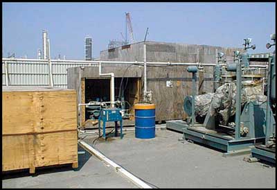
Figure 1 shows temporary field tubing that supplies oil mist to the bearing points of a turbine drive pump row.
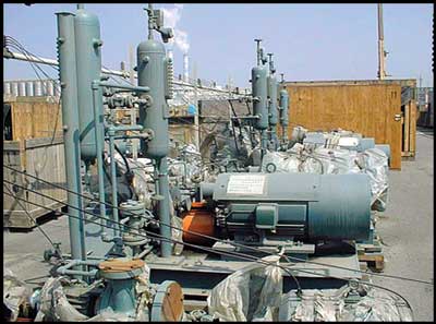
Figure 2 shows a similar installation, feeding oil mist to pump and motor bearings.
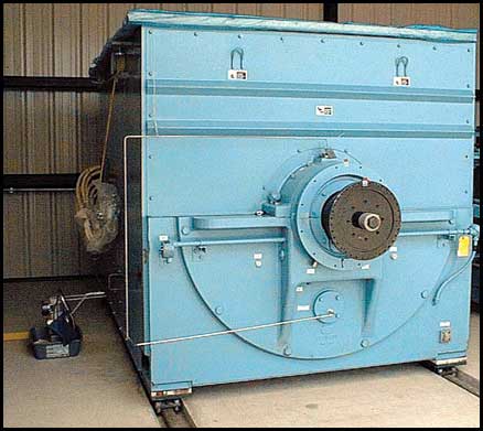
Figure 3 illustrates construction site storage oil mist supply lines that run to a vertical mechanical drive turbine as well as to a large feed pump motor.
Storage for Stand-by Capacity
The third and last case of machinery storage protection arises when standby capability of inactive equipment is desired. Reference 1 describes such a case. It appears as though there are no limits to the ingenuity displayed by operators, as long as a “do nothing and take your chances” stance is not taken. In addition, best practice dictates that all preventive maintenance be logged by item number in the maintenance log.
While the case of extended standby protection does not seem to present a problem for process pumps and other general-purpose equipment, especially where oil-mist lubrication is installed and operating, it might well be a challenge to operators of steam and gas turbines as well as reciprocating engines and compressors. One company has had excellent success with a program it developed in-house for standby storage of critical machinery, particularly gas turbines. Following is one manufacturer’s recommendations for the standby protection of gas engines or gas engine-driven compressors:
Drain the water jackets and then circulate the proper compound (see Table 1) through the jackets making sure that all surfaces in the jacket are reached. Drain the system and plug all openings.
Lubrication Systems of Engines
For engine lubrication systems, the following procedure is recommended:
- Drain the lubricating oil system, including filters, coolers, governors and mechanical lubricators. Flush the complete system with standard petroleum solvent that will take the oil off the surfaces. Use an external pump to force solvent through the system. Spray the interior of the crankcase thoroughly, then drain.
- Refill with Product 4 to the minimum level, just enough to ensure pump suction at all times, in each case. Crank the mechanical lubricator by hand until all lines are purged. Where compressors are used, be sure to flood the compressor rod packing.
- Using air pressure or any other convenient means, turn the engine at sufficient speed and for a sufficient length of time to thoroughly circulate the compound through the engine.
- Stop and drain the engine sump, filters, coolers, governor, lubricators, etc. Plug all openings.
- Remove the spark plugs or gas injection valves and spray with Product 2 inside the cylinders, covering all surfaces. At the same time, rotate the engine by hand so that each piston is on bottom dead center when that particular cylinder is being sprayed.
- After this operation the engine should not be turned or barred over until it is ready to be placed in service. Tag the engine in several prominent places with warning tags.
- Where compressors are involved, including scavenging air compressors, remove the valves and spray inside the cylinder to cover all surfaces. Dip the compressor valves in Product 1 and drain off the excess. Reassemble valves in place.
Reference Bloch, H. and Shamim, A. 1995. Oil Mist Lubrication: Practical Applications. Lilburn, G: Fairmont Press.
Related Articles

OEE: Overall Equipment Effectiveness
What the Pump Was Designed to Do and Why it Doesn't Do it
What is Wrong with the Modern Centrifugal Pump?

Digging Up Savings: Go with the Flow
Chain Drive Design Recommendations

Classifying Chemicals to Assure Effective Sealing
