Cavitation
The McNally Institute
 What is Cavitation?
Cavitation means that cavities are forming in the liquid that we are pumping. When these cavities form at the suction of the pump several things happen all at once.
- We experience a loss in capacity.
- We can no longer build the same head (pressure)
- The efficiency drops.
- The cavities or bubbles will collapse when they pass into the higher regions of pressure causing noise, vibration, and damage to many of the components.
The cavities form for five basic reasons and it is common practice to lump all of them into the general classification of cavitation. This is an error because we will learn that to correct each of these conditions we must understand why they occur and how to fix them. Here they are in no particular order:
- Vaporization
- Air ingestion
- Internal recirculation
- Flow turbulence
- The Vane Passing Syndrome
Vaporization
A fluid vaporizes when its pressure gets too low, or its temperature too high. All centrifugal pumps have a required head (pressure) at the suction side of the pump to prevent this vaporization. This head requirement is supplied to us by the pump manufacturer and is calculated with the assumption that fresh water at 68 degrees Fahrenheit (20 degrees Centigrade) is the fluid being pumped.
Since there are losses in the piping leading from the source to the suction of the pump we must determine the head after these losses are calculated. Another way to say this is that a Net Positive Suction Head is Required (N.P.S.H.R.) to prevent the fluid from vaporizing.
We take the Net Positive Suction Head Available (N.P.S.H.A.) subtract the Vapor Pressure of the product we are pumping, and this number must be equal to or greater than the Net Positive Suction Head Required.
To cure vaporization problems you must either increase the suction head, lower the fluid temperature, or decrease the N.P.S.H. Required. We shall look at each possibility:
Increase the suction head
- Raise the liquid level in the tank
- Raise the tank
- Put the pump in a pit
- Reduce the piping losses. These losses occur for a variety of reasons that include:
- The system was designed incorrectly. There are too many fittings and/or the piping is too small in diameter.
- A pipe liner has collapsed.
- Solids have built up on the inside of the pipe.
- The suction pipe collapsed when it was run over by a heavy vehicle.
- A suction strainer is clogged.
- Be sure the tank vent is open and not obstructed. Vents can freeze in cold weather
- Something is stuck in the pipe, It either grew there or was left during the last time the system was opened . Maybe a check valve is broken and the seat is stuck in the pipe.
- The inside of the pipe, or a fitting has corroded.
- A bigger pump has been installed and the existing system has too much loss for the increased capacity.
- A globe valve was used to replace a gate valve.
- A heating jacket has frozen and collapsed the pipe.
- A gasket is protruding into the piping.
- The pump speed has increased.
- Install a booster pump
- Pressurize the tank
Lower the fluid temperature
- Injecting a small amount of cooler fluid at the suction is often practical.
- Insulate the piping from the sun’s rays.
- Be careful of discharge recirculation lines, they can heat up the suction fluid.
Reduce the N.P.S.H. Required
- Use a double suction pump. This can reduce the N.P.S.H.R. by as much as 27% or in some cases it will allow you to raise the pump speed by 41%
- Use a lower speed pump
- Use a pump with a larger impeller eye opening.
- If possible install an Inducer. These inducers can cut N.P.S.H.R. by almost 50%.
- Use several smaller pumps. Three half capacity pumps can be cheaper than one large pump plus a spare. This will also conserve energy at lighter loads.
- It is a general rule of thumb that hot water and gas free hydrocarbons can use up to 50% of normal cold water N.P.S.H. requirements, or 10 feet (3 meters), whichever is smaller. I would suggest you use this as a safety margin rather than design for it.
Air ingestion
A centrifugal pump can handle 0.5% air by volume. At 6% air the results can be disastrous. Air gets into as system in several ways that include:
- Through the stuffing box. This occurs in any packed pump that lifts liquid, pumps from a condenser, evaporator or any piece of equipment that runs in vacuum.
- Valves above the water line.
- Through leaking flanges
- Vortexing fluid.
- A bypass line has been installed too close to the suction.
- The suction inlet pipe is out of fluid. This can occur when the level gets too low or there is a false reading on the gauge because the float is stuck on a corroded rod.
Both vaporization and air ingestion have an affect on the pump. The bubbles collapse as they pass from the eye of the pump to the higher pressure side of the impeller. Air ingestion seldom causes damage to the impeller or casing. The main effect of air ingestion is loss of capacity.
Although air ingestion and vaporization both occur they have separate solutions. Air ingestion is not as severe as vaporization and seldom causes damage, but it does lower the capacity of the pump.
Internal Recirculation
This condition is visible on the leading edge of the impeller, and will usually be found at the discharge tip working its way back to the suction. It can also be found at the suction eye of the pump.
As the name implies the fluid recirculates increasing its velocity until it vaporizes and then collapses in the surrounding higher pressure. This has always been a problem with low NPSH pumps and the term SPECIFIC SUCTION SPEED was coined to give you a guide in determining how close you have to operate to the B.E.P. of a pump to prevent the problem.
The higher the number the smaller the window in which you have to operate. The numbers range between 3,000 and 20,000. Water pumps should stay between 3,000 and 12,000. Here is the formula to determine the suction specific speed number of your pump:
rpm = Pump speed
gpm = Gallons per minute or liters per second of the largest impeller at its BEP
Head= Net positive suction head required at that rpm
- For a double suction pump the flow is divided by 2 since there are 2 impeller eyes
- Try to buy pumps lower than 8500.(5200 metric ) forget those over 12000 (8000 metric) except for extreme circumstances.
- Mixed hydrocarbons and hot water at 9000 to 12000 (5500 to 7300 metric) or higher, can probably operate satisfactorily.
- High specific speed indicates the impeller eye is larger than normal, and efficiency may be compromised to obtain a low NPSH required.
- Higher values of specific speed may require special designs, and operate with some cavitation.
- Normally a pump operating 50% below its best efficiency point (B.E.P.) is less reliable.
With an open impeller pump you can usually correct the problem by adjusting the impeller clearance to the manufacturers specifications. Closed impeller pumps present a bigger problem and the most practical solution seems to be to contact the manufacturer for an evaluation of the impeller design and a possible change in the design of the impeller or the wear ring clearances.
Turbulence
We would prefer to have liquid flowing through the piping at a constant velocity. Corrosion or obstructions can change the velocity of the liquid and any time you change the velocity of a liquid you change its pressure. Good piping layouts would include:
- Ten diameters of pipe between the pump suction and the first elbow.
- In multiple pump arrangements we would prefer to have the suction bells in separate bays so that one pump suction will not interfere with another. If this is not practical a number of units can be installed in a single large sump provided that :
- The pumps are located in a line perpendicular to the approaching flow.
- There must be a minimum spacing of at least two suction diameters between pump center lines.
- All pumps are running.
- The upstream conditions should have a minimum straight run of ten pipe diameters to provide uniform flow to the suction bells.
- Each pump capacity must be less than 15,000 gpm..
- Back wall clearance distance to the centerline of the pump must be at least 0.75 of the suction diameter.
- Bottom clearance should be approximately 0.30 (30%) of the suction diameter
- The minimum submergence should be as follows:
| FLOW MINIMUM | SUBMERGENCE |
| 20,000 GPM | 4 FEET |
| 100,000 GPM | 8 FEET |
| 180,000 GPM | 10 FEET |
| 200,000 GPM | 11 FEET |
| 250,000 GPM | 12 FEET |
The metric numbers are:
| FLOW MINIMUM | SUBMERGENCE |
| 4,500 M3/HR | 1.2 METERS |
| 22,500 M3/HR | 2.5 METERS |
| 40,000 M3/HR | 3.0 METERS |
| 45,000 M3/HR | 3.4 METERS |
| 55,000 M3/HR | 3.7 METERS |
The Vane Passing Syndrome
You will notice damage to the tip of the impeller caused by its passing too close to the pump cutwater. The velocity of the liquid increases if the clearance is too small lowering the pressure and causing local vaporization. The bubbles collapse just beyond the cutwater and there is where you should look for volute damage. You will need a flashlight and mirror to see the damage unless it has penetrated to the outside of the volute.
The damage is limited to the center of the impeller and does not extend into the shrouds. You can prevent this problem if you keep a minimum impeller tip to cutwater clearance of 4 % of the impeller diameter in the smaller impeller sizes (less than 14′ or 355 mm.) and 6% in the larger impeller sizes (greater than 14″ or 355 mm.).
To prevent excessive shaft movement bulkhead rings can be installed in the suction eye. At the discharge rings can be manufactured to extend from the walls to the impeller shrouds.
Cavitation means different things to different people. It has been described as:
- A reduction in pump capacity.
- A reduction in the head of the pump.
- The formation of bubbles in a low pressure area of the pump volute.
- A noise that can be heard when the pump is running.
- Damaged that can be seen on the pump impeller and volute.
- Just what then is this thing called cavitation? Actually it is all of the above. In another section of this series I described the several types of cavitation, so in this paper I want to talk about another side of cavitation and try to explain why the above happens.
Cavitation implies cavities or holes in the fluid we are pumping. These holes can also be described as bubbles, so cavitation is really about the formation of bubbles and their collapse. Bubbles form when ever liquid boils. Be careful not to associate boiling with hot to the touch. Liquid oxygen will boil and no one would ever call that hot.
Fluids boil when the temperature of the fluid gets too hot or the pressure on the fluid gets too low. At an ambient sea level pressure of 14.7 psia (one bar) water will boil at 212°F. (100°C) If you lower the pressure on the water it will boil at a much lower temperature and conversely if you raise the pressure the water will not boil until it gets to a higher temperature. There are charts available to give you the exact vapor pressure for any temperature of water. If you fall below this vapor pressure the water will boil. As an example:
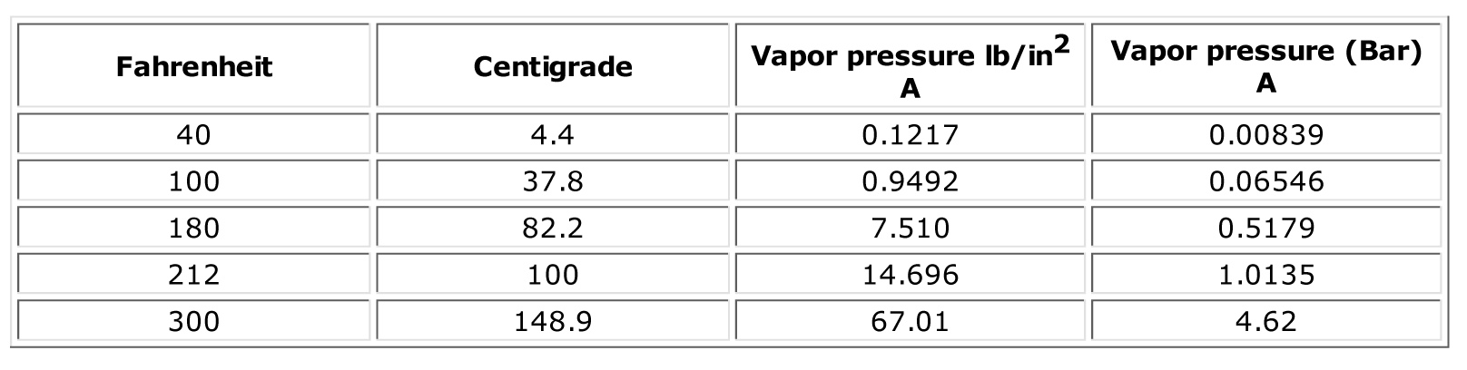 Please note that I am using absolute not gauge pressure. It is common when discussing the suction side of a pump to keep everything in absolute numbers to avoid the use of minus signs. So instead of calling atmospheric pressure zero, we say one atmosphere is 14.7 psia at seal level and in the metric system the term commonly used is one bar, or 100 kPa if you are more comfortable with those units.
Now we will go back to the first paragraph and see if we can clear up some of the confusion:
The capacity of the pump is reduced
- This happens because bubbles take up space and you cannot have bubbles and liquid in the same place at the same time.
- If the bubble gets big enough at the eye of the impeller, the pump will lose its suction and will require priming.
The head is often reduced
- Bubbles unlike liquid are compressible. It is this compression that can change the head.
The bubbles form in a lower pressure area because they cannot form in a high pressure area.
- You should keep in mind that as the velocity of a fluid increase, the pressure of the fluid decreases. This means that high velocity liquid is by definition a lower pressure area. This can be a problem any time a liquid flows through a restriction in the piping, volute, or changes direction suddenly. The fluid will accelerate as it changes direction. The same acceleration takes place as the fluid flows in the small area between the tip of the impeller and the volute cut water.
A noise is heard
- Any time a fluid moves faster than the speed of sound, in the medium you are pumping, a sonic boom will be heard. The speed of sound in water is 4800 feet per second (1480 meters/sec) or 3,273 miles per hour (5,267 kilometers per hour).
Pump parts show damage
- The bubble tries to collapse on its self. This is called imploding, the opposite of exploding. The bubble is trying to collapse from all sides, but if the bubble is laying against a piece of metal such as the impeller or volute it cannot collapse from that side, so the fluid comes in from the opposite side at this high velocity proceeded by a shock wave that can cause all kinds of damage. There is a very characteristic round shape to the liquid as it bangs against the metal creating the impression that the metal was hit with a “ball peen hammer”.
- This damage would normally occur at right angles to the metal, but experience shows that the high velocity liquid seems to come at the metal from a variety of angles. This can be explained by the fact that dirt particles get stuck on the surface of the bubble and are held there by the surface tension of the fluid. Since the dirt particle has weakened the surface tension of the bubble it becomes the weakest part and the section where the collapse will probably take place. The higher the capacity of the pump the more likely cavitation will occur. Some plants inject air into the suction of the pump to reduce this capacity and lower the possibility of cavitation. They choose this solution because they fear that throttling the discharge of a high temperature application will heat the fluid in the pump and almost guarantee the cavitation. In this case air injection is the better choice of two evils.
High specific speed pumps have a different impeller shape that allows them to run at high capacity with less power and less chance of cavitating. You normally find this impeller in a pipe shaped casing rather than the volute type of casing that you commonly see.
Related Articles
Motor Brush Facts and Maintenance
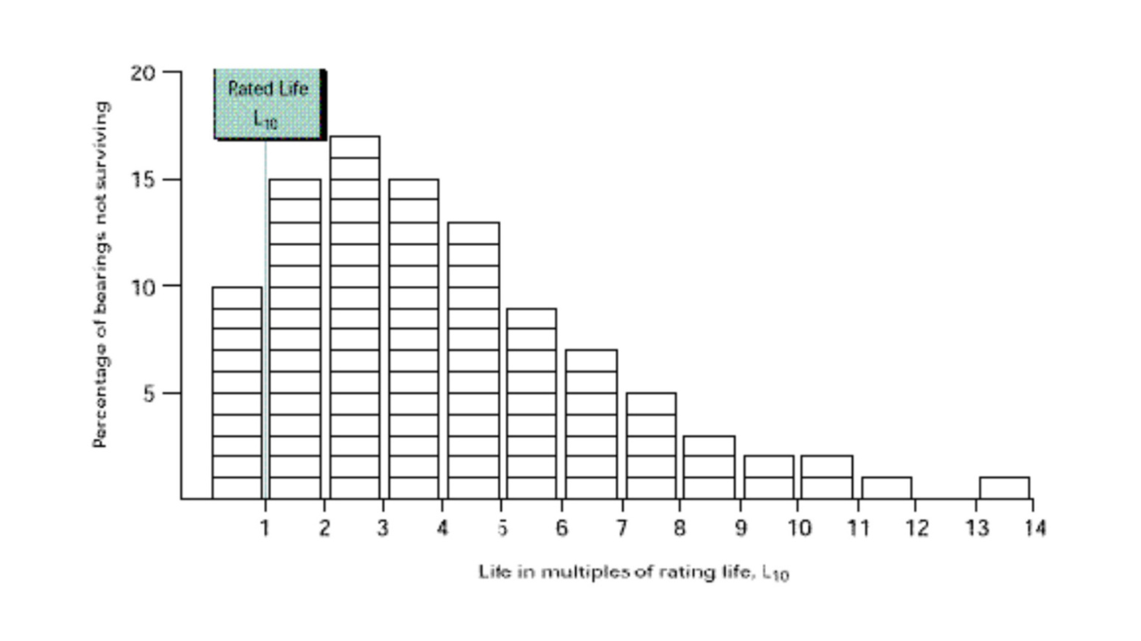
Basis for Bearing Life Calculation
The Affinity Laws for Rotary, Positive Displacement Pumps 13-6
Pump Technology Balancing Tradition & Innovation
The ANSI Pump Standard 14-5