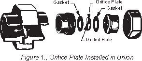
Flow through Orifices
womackmachine.com
Hydraulic Oil Flow through Orifices
The chart shows approximate pressure drops which may be expected at various flows rates through sharp edge orifices for petroleum type hydraulic oil. It may be used for designing limiting flow orifices in hydraulic systems. Chart values must be considered as approximate because a number of factors such as specific gravity, orifice efficiency, plumbing ahead of and behind the orifice may cause variations from the values shown.
By making the orifice with a knife edge, it becomes insensitive to temperature, and the flow and pressure drop will remain the same over a reasonable range of oil temperatures (and viscosity changes).
Specific gravity of the fluid makes a significant difference in the pressure drop through a given orifice, and increases approximately as the square of the increase in specific gravity, The chart was calculated for a fluid with 0.9 specific gravity, a close approximation for all petroleum hydraulic oils. Using a heavier fluid, a multiplying factor should be applied to chart values. For example, to find the pressure drop of water, with a specific gravity of 1.00:
(1.00)2 ÷ (0.9)2 = 1.00 ÷ 0.81 = 1.23 multiplying factor.
Multiply all chart values by 1.23 for water flow.
The chart was calculated from information furnished by Double A Products Co., in which the constant 23.5 was developed by trial and error for average orifices. For values not shown in the chart, use this formula:
Pressure Drop (ΔP) = [GPM ÷ (23.5 x A)]2
in which, A = Orifice Area, Sq. ln.
Figures in this chart are PSI pressure drops across sharp edge orifices, petroleum type hydraulic oil.
| Orifice Diameter, Inches | ||||||||||||||||||
| GPM | 3/64 | 1/16 | 5/64 | 3/32 | 7/64 | 1/8 | 9/64 | 5/32 | 11/64 | 3/16 | 13/64 | 7/32 | 15/64 | 1/4 | 5/16 | 3/8 | 7/16 | 1/2 |
| 3 | 5440 | 1730 | 710 | 333 | 184 | 108 | 68 | 44 | 30 | 21 | 16 | 12 | 9 | 7 | 3 | 1 | – – – | – – – |
| 5 | – – – | 4800 | 1970 | 925 | 512 | 300 | 188 | 123 | 84 | 59 | 43 | 32 | 24 | 19 | 8 | 4 | 2 | 1 |
| 10 | – – – | – – – | – – – | 3700 | 2050 | 1200 | 750 | 490 | 336 | 238 | 172 | 128 | 97 | 75 | 31 | 15 | 8 | 5 |
| 15 | – – – | – – – | – – – | – – – | 4600 | 2700 | 1690 | 1100 | 757 | 534 | 388 | 288 | 219 | 169 | 69 | 33 | 18 | 11 |
| 20 | – – – | – – – | – – – | – – – | – – – | 4800 | 3000 | 1968 | 1345 | 950 | 690 | 513 | 390 | 300 | 123 | 59 | 32 | 19 |
| 30 | – – – | – – – | – – – | – – – | – – – | – – – | 6750 | 4430 | 3025 | 2135 | 1550 | 1155 | 875 | 675 | 275 | 135 | 72 | 42 |
| 40 | – – – | – – – | – – – | – – – | – – – | – – – | – – – | – – – | 5380 | 3800 | 2760 | 2050 | 1555 | 1205 | 495 | 235 | 128 | 75 |
| 50 | – – – | – – – | – – – | – – – | – – – | – – – | – – – | – – – | – – – | – – – | 4310 | 3205 | 2430 | 1880 | 770 | 370 | 200 | 118 |
| 60 | – – – | – – – | – – – | – – – | – – – | – – – | – – – | – – – | – – – | – – – | – – – | 4615 | 3500 | 2705 | 1110 | 535 | 288 | 170 |
| 70 | – – – | – – – | – – – | – – – | – – – | – – – | – – – | – – – | – – – | – – – | – – – | – – – | 4765 | 3685 | 1510 | 725 | 390 | 230 |
| 80 | – – – | – – – | – – – | – – – | – – – | – – – | – – – | – – – | – – – | – – – | – – – | – – – | – – – | 4810 | 1970 | 950 | 510 | 300 |
| 100 | – – – | – – – | – – – | – – – | – – – | – – – | – – – | – – – | – – – | – – – | – – – | – – – | – – – | – – – | 3080 | 1480 | 800 | 470 |
Caution! Calculated values of pressure drop are approximate. Drill orifice undersize to start and run a preliminary test; then enlarge as necessary using standard twist drills. Countersink finished hole for a sharp edge.
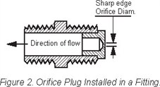
The orifice plug must be machined by the user. It should be a press fit in the fitting. Remember, the sharper the edge of the orifice, the less the flow and pressure drop will be affected by changes in the fluid viscosity and temperature.
Figures in the chart are theoretical SCFM air flows through perfect orifices (See text).
Compressed Air Flow Through Orifices
| PSI Across Orifice | Orifice Diameter in Inches | ||||||||||
| 1/64 | 1/32 | 1/16 | 1/8 | 1/4 | 3/8 | 1/2 | 5/8 | 3/4 | 7/8 | 1 | |
| 5 | 0.062 | 0.248 | 0.993 | 3.97 | 15.9 | 35.7 | 63.5 | 99.3 | 143 | 195 | 254 |
| 6 | 0.068 | 0.272 | 1.09 | 4.34 | 17.4 | 39.1 | 69.5 | 109 | 156 | 213 | 278 |
| 7 | 0.073 | 0.293 | 1.17 | 4.68 | 18.7 | 42.2 | 75.0 | 117 | 168 | 230 | 300 |
| 9 | 0.083 | 0.331 | 1.32 | 5.30 | 21.2 | 47.7 | 84.7 | 132 | 191 | 260 | 339 |
| 12 | 0.095 | 0.379 | 1.52 | 6.07 | 24.3 | 54.6 | 97.0 | 152 | 218 | 297 | 388 |
| 15 | 0.105 | 0.420 | 1.68 | 6.72 | 26.9 | 60.5 | 108 | 168 | 242 | 32 | 430 |
| 20 | 0.123 | 0.491 | 1.96 | 7.86 | 31.4 | 70.7 | 126 | 196 | 283 | 385 | 503 |
| 25 | 0.140 | 0.562 | 2.25 | 8.98 | 35.9 | 8039 | 144 | 225 | 323 | 440 | 575 |
| 30 | 0.158 | 0.633 | 2.53 | 10.1 | 40.5 | 91.1 | 162 | 253 | 365 | 496 | 648 |
| 35 | 0.176 | 0.703 | 2.81 | 11.3 | 45.0 | 101 | 180 | 281 | 405 | 551 | 720 |
| 40 | 0.194 | 0.774 | 3.10 | 12.4 | 49.6 | 112 | 198 | 310 | 446 | 607 | 793 |
| 45 | 0.211 | 0.845 | 3.38 | 13.5 | 54.1 | 122 | 216 | 338 | 487 | 662 | 865 |
| 50 | 0.229 | 0.916 | 3.66 | 14.7 | 58.6 | 132 | 235 | 366 | 528 | 718 | 938 |
| 60 | 0.264 | 1.03 | 4.23 | 16.9 | 67.6 | 152 | 271 | 423 | 609 | 828 | 1082 |
| 70 | 0.300 | 1.20 | 4.79 | 19.2 | 76.7 | 173 | 307 | 479 | 690 | 939 | 1227 |
| 80 | 0.355 | 1.34 | 5.36 | 21.4 | 85.7 | 193 | 343 | 536 | 771 | 1050 | 1371 |
| 90 | 0.370 | 1.48 | 5.92 | 23.7 | 94.8 | 213 | 379 | 592 | 853 | 1161 | 1516 |
| 100 | 0.406 | 1.62 | 6.49 | 26.0 | 104 | 234 | 415 | 649 | 934 | 1272 | 1661 |
| 110 | 0.441 | 1.76 | 7.05 | 28.2 | 113 | 254 | 452 | 705 | 1016 | 1383 | 1806 |
| 120 | 0.476 | 1.91 | 7.62 | 30.5 | 122 | 274 | 488 | 762 | 1097 | 1494 | 1951 |
| 125 | 0.494 | 1.98 | 7.90 | 31.6 | 126 | 284 | 506 | 790 | 1138 | 1549 | 2023 |
Values in the chart are taken from the compressed Air and Gas Handbook, published by the Compressed Air and Gas Institute, 2130 Keith Building, Cleveland, Ohio 44115. Chart is based on 100% coefficient of flow (theoretical).
For well rounded entrance multiply values by 0.97. For sharp edged orifices with abrupt entrance, a multiplier of 0.65 may be used. All values are calculated, and are approximate. They are intended for estimating purposes only.
Vacuum Flow Through Orifices
Figures in the chart are estimated SCFM air flows through the influences of vacuum.
| Vacuum, Inches Hg. | Orifice Diamter in Inches | ||||||||||
| 1/64 | 1/32 | 1/16 | 1/8 | 1/4 | 3/8 | 1/2 | 5/8 | 3/4 | 7/8 | 1 | |
| 2″ | 0.018 | 0.074 | 0.300 | 1.20 | 4.78 | 10.8 | 18.1 | 30.0 | 43.0 | 58.8 | 76.5 |
| 4″ | 0.026 | 0.100 | 0.420 | 1.68 | 6.74 | 15.2 | 27.0 | 42.2 | 60.6 | 82.6 | 108 |
| 6″ | 0.032 | 0.128 | 0.517 | 2.06 | 8.25 | 18.5 | 33.0 | 51.7 | 74.0 | 101 | 131 |
| 8″ | 0.037 | 0.148 | 0.595 | 2.37 | 9.52 | 21.4 | 38.5 | 59.5 | 85.3 | 116 | 152 |
| 10″ | 0.041 | 0.165 | 0.660 | 2.64 | 10.6 | 23.8 | 42.3 | 66.2 | 95.2 | 130 | 169 |
| 12″ | 0.045 | 0.180 | 0.725 | 2.89 | 11.6 | 26.0 | 46.3 | 72.6 | 104 | 142 | 185 |
| 14″ | 0.048 | 0.195 | 0.780 | 3.12 | 12.4 | 28.0 | 50.0 | 78.0 | 112 | 153 | 200 |
| 18″ | 0.055 | 0.220 | 0.880 | 3.53 | 14.0 | 31.8 | 56.5 | 88.0 | 127 | 173 | 225 |
| 24″ | 0.063 | 0.250 | 1.00 | 4.04 | 16.2 | 36.4 | 64.6 | 101 | 145 | 198 | 258 |
This chart shows estimated flows through a practical orifice, and are about 2/3rds the theoretical flow calculated for a perfect orifice.
The chart may be useful in estimating the flow capacity of a vacuum pump used to furnish vacuum to grippers used in handling sheet material used in the packaging, printing, and similar industries.
Please remember these values are approximate, as many other factors in the system would cause variations in flow.
To read about pumps, click here.
© 1988 by Womack Machine Supply Co. This company assumes no liability for errors in data nor in safe and/or satisfactory operation of equipment designed from this information.
Related Articles
Adhesives Assure Fastener Reliability

Protecting Cooling Water Systems – Part 1

Protecting Cooling Water Systems – Part 2

How do Control Valves Work?
Should Jack Screws be tight or backed off?

Guided Growth: Mentoring Humans and Humanoids in Complex Systems