A cyclone separator is used to separate larger, heavy particles from smaller, lighter particles. It does that by using a spinning column of gas to force the larger, heavier particles out to the walls of the cyclone. By changing the ratio of its dimensions, they can used to remove particles larger than a selected size.
A tornado can lift cars from the ground and hurl them hundreds of meters away. Chickens and ducks can be hurled kilometers away. The story of fish falling from the sky is explained by the power of a tornado to lift materials kilometers into the sky. The spinning vortex of air separates and segregates heavy and light objects. The heavy objects drop out sooner and the light objects are carried further. Cyclone separators and hydro cyclones work the same way.
DESIGN OF A CYCLONE SEPARATOR
The most common type of cyclone separator is the tangential inlet, axial discharge style shown in Figure No. 1. The second often-used design is the axial inlet, axial discharge type which uses slanting vanes to start the air spinning. The tangential inlet cyclone covers a much larger range of throughput and particle sizes than the axial inlet design and is cheaper to make. Both work on the principle of using a spinning column of air to separate particles of different weights. A hydro cyclone spins a column of liquid instead of gas.
Figure 1 Tangential inlet cyclone showing gas flows
Cyclones are used to separate liquids and solids from a gas stream. Hydro cyclones separate solids from liquids or one liquid from another of different density. The inlet stream enters the top chamber at high velocity and spins around the inside wall of the chamber. Any material above the weight that can be held up by the moving stream is flung out to the wall of the chamber and begins to slide down to the bottom outlet.
The stream then spirals down the cyclone top and enters into the conical bottom as more comes in from behind. Since the cone tapers inward, the available volume to take the full stream decreases. The speed of the stream increases to keep a constant mass flow through the cyclone. The stream velocity is higher and spinning faster as it moves down the cone. So fast in fact, that the centrifugal forces on the smaller particles remaining in the stream overcome the carrying velocity and are flung out to the wall. As the stream moves down the cone the particles being separated out become smaller and smaller.
Have you seen cigarette smoke sucked out of a moving car window? It is a natural law that a moving stream of air produces reduced pressure at right angles to its direction of motion. The ‘moving’ air at the open window is at a lower pressure than the air in the car and the smoke is drawn to the window.
The same law applies in a cyclone. The stream spinning against the inside wall of the cyclone produces a low-pressure area at right angles to its motion. The low-pressure area develops in the middle of the cyclone and becomes a reverse spiraling column of fast moving low-pressure gas exiting the outlet nozzle in the top chamber.
CRITICAL SHAPE AND FLOW PARAMETERS
The critical factors affecting cyclone operation are sufficiently high gas stream velocity, particle agglomeration characteristics (tendency to join and stick together) and cyclone diameter-to-length ratios of the top cylinder and cone. By altering the size ratios of the cyclone sections, it is possible to design cyclones that will remove (cut) particles above a specific size/weight proportion.
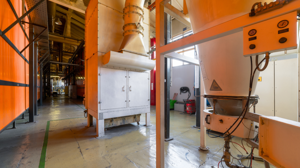
Figure 2 Filtering and ventilating equipment; filter cyclone and electrostatic filter; courtesy of Nordroden from Getty Images via Canva
CONFIGURATION OF A CYCLONE IN USE
A cyclone requires a high velocity, moving stream of gas to be consistently fed to it. A fan is used to push or suck the gas through the cyclone. The flow needs to be steady and not fluctuate otherwise the counter-moving vortexes within the cyclone cannot develop and be sustained.
The bottom outlet is required to be airtight, so no air bleeds into the low-pressure central vortex. If air does leak through the bottom outlet the particles on the inside wall of the cyclone are re-entrained in the air steam and are sucked up the inside vortex and out the gas outlet nozzle. A rotary valve or an automated twin butterfly valve air-lock arrangement can be used on the bottom outlet. If a dustbin is installed on the bottom of the cyclone empty the bin regularly so the dust does not fill up and enter into the cyclone.
Cyclones can be run in series or in parallel. When in series they are often configured so that the first one takes out the big particles while the next takes out smaller particles. Series operation produces high-pressure drops and requires more powerful fans to force the stream through the system.
High particle velocities within the cyclone will wear away the walls. For aggressive materials the internal walls will require lining or use of a harder material than the particles. If rubber is selected check that the particle hardness and shape do not rip into the soft rubber. At times harder urethane plastics and even ceramic linings maybe required.
References – Cyclone Separator Overview
Muhammad E. Fayed & Lambert Otten, Handbook of Powder Science and Technology Chapter 15, 1997
Perry Robert H, Perry’s Chemical Engineer’s Handbook 1984,
Mike Sondalini is a Senior Consultant at PWWEAM System-of-Reliability. BEng(Hons), MBA, CPEng. As a consultant and trainer, Mike was able to present his insights to his clients, suggesting innovative approaches to plant and equipment reliability. Their feedback was resoundingly positive. Efforts which earned him an international reputation for articulate, out-of-the-box articles on plant and equipment reliability, life-cycle EAM, maintenance management, work quality assurance, and team building. After decades of dedicated research, Mike authored “Industrial Manufacturing Wellness: The Complete Guide to Successful Enterprise Asset Management” a revolutionary approach on how maintenance and physical asset management systems should be run, the book detailed who, what, where, when, why, and how outstanding reliability could be achieved. Each step based in scientific and mathematical understanding to ensure repeatability of results and optimal outcomes.
The affinity laws accurately predict the affect of changing the speed of a centrifugal or rotary pump, and they also do a fairly good job of predicting the affect of changing the diameter of a centrifugal pump. In another paper (02-01) we discussed the affinity laws as they apply to centrifugal pumps, but in this paper we will look at their use with rotary pumps.
The affinity laws accurately predict the affect of changing the speed of a centrifugal or rotary pump, and they also do a fairly good job of predicting the affect of changing the diameter of a centrifugal pump. In another paper (02-01) we discussed the affinity laws as they apply to centrifugal pumps, but in this paper we will look at their use with rotary pumps.
The previous article in this series, "Understanding Shaft Alignment: Thermal Growth," explained thermal growth and its affect on proper equipment alignment. A practical example involves a recent project at a wastewater treatment plant in Cleveland that needed realistic cold alignment targets for a 3600 rpm compressor to reach their accurate alignment targets.
The previous article in this series, "Understanding Shaft Alignment: Thermal Growth," explained thermal growth and its affect on proper equipment alignment. A practical example involves a recent project at a wastewater treatment plant in Cleveland that needed realistic cold alignment targets for a 3600 rpm compressor to reach their accurate alignment targets.
Get mechanical seals working properly. Mechanical seals are used to keep the bulk contents of rotating equipment such as pumps and compressors from escaping. They do this by sealing the shaft that protrudes from the casing. They require quality installation and operation conditions for a long life. Keywords: precision assembly, barrier fluid, stationary seal, rotary seal, alignment.
Get mechanical seals working properly. Mechanical seals are used to keep the bulk contents of rotating equipment such as pumps and compressors from escaping. They do this by sealing the shaft that protrudes from the casing. They require quality installation and operation conditions for a long life. Keywords: precision assembly, barrier fluid, stationary seal, rotary seal, alignment.
I was asked recently to investigate and solve an overheating problem in a mobile hydraulics application. The hydraulic system that was overheating comprised a diesel-hydraulic power unit, which was being used to power a pipe-cutting saw. The saw was designed for sub-sea use and was connected to the hydraulic power unit on the surface via a 710-foot umbilical. The operating requirements for the saw were 24 gpm at 3000 psi. Heating of hydraulic fluid in operation is caused by inefficiencies. Inefficiencies result in losses of input power, which are converted to heat. A hydraulic system's heat load is equal to the total power lost (PL) through inefficiencies.
I was asked recently to investigate and solve an overheating problem in a mobile hydraulics application. The hydraulic system that was overheating comprised a diesel-hydraulic power unit, which was being used to power a pipe-cutting saw. The saw was designed for sub-sea use and was connected to the hydraulic power unit on the surface via a 710-foot umbilical. The operating requirements for the saw were 24 gpm at 3000 psi. Heating of hydraulic fluid in operation is caused by inefficiencies. Inefficiencies result in losses of input power, which are converted to heat. A hydraulic system's heat load is equal to the total power lost (PL) through inefficiencies.
The valve is one of the most basic and indispensable components of our modern technological society. It is essential to virtually all manufacturing processes and every energy production and supply system. Yet it is one of the oldest products known to man, with a history of thousands of years.
The valve is one of the most basic and indispensable components of our modern technological society. It is essential to virtually all manufacturing processes and every energy production and supply system. Yet it is one of the oldest products known to man, with a history of thousands of years.
Machine conditions change from the time the machine is off line to when it is running under normal operating conditions. Some of these changes are due to process forces (e.g., fluid pressures, airflow, etc.). The most notable of these changes is the change in the temperature of the machine bearings and supports. This is called the machine's thermal growth.
Machine conditions change from the time the machine is off line to when it is running under normal operating conditions. Some of these changes are due to process forces (e.g., fluid pressures, airflow, etc.). The most notable of these changes is the change in the temperature of the machine bearings and supports. This is called the machine's thermal growth.
Expansion joints for pipework are often made from corrugated metal, especially when handling liquids or for operating pressures significantly above atmospheric. Metal expansion joints are outside the scope of the ESA guide.
Expansion joints for pipework are often made from corrugated metal, especially when handling liquids or for operating pressures significantly above atmospheric. Metal expansion joints are outside the scope of the ESA guide.