Disc Couplings Dump Downtime
Kevin Remack
Want to expand coupling life? Who doesn’t? You may want to look into advanced-design disc couplings.
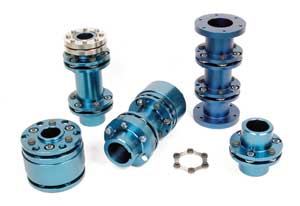
These couplings feature discs with optimized profile and thickness to provide a higher torque-to-outside-diameter ratio, higher service factors and up to 50 percent greater misalignment capability. All this provides for smaller reactionary forces on bearings compared to conventional disc couplings, which helps achieve infinite coupling life in properly specified applications.
The advanced-design variety utilizes high-grade stainless steels for strength and resistance to hostile environments, and provides the torsionally rigid, no-backlash operation characteristic of disc couplings. Typical applications of disc couplings are on high-speed machinery where non-lubricated, low-maintenance and long-life couplings are desired. However, with its benefits, disc couplings are replacing other coupling styles in redesigns and retrofits.
Benefits of Disc Couplings
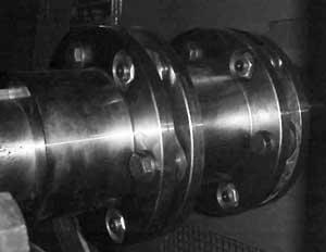
Disc couplings offer plants the benefit of reduced downtime through maintenance-free operation and running inspection.
By design, a disc coupling has no moving parts and requires no lubrication, reducing equipment maintenance costs associated with shutdown, motor/equipment removal and labor. Without having to remove a motor or reposition the equipment side, which are typical risks of realignment, breakage and safety concerns are eliminated.
Inspection of disc couplings is also plant-friendly. They can be inspected for condition, wear and performance without disassembly.
Additionally, you can inspect them while the equipment is running with the use of a strobe light. Under a strobe, you can see the discs flex and move. You can also see any damage. In the event that a disc pack needs replacement, certain coupling styles allow for a center section (containing the disc packs) to be removed without removing either shaft hub.

Installation Tips
A flexible disc coupling is designed for long life when operated within the torque and alignment limits as set forth in the manufacturer’s catalog and installation instructions.
The installation of a flexible disc coupling is critical. Various problems can arise during mounting of the hubs and the coupling assembly process.
Burrs, dirt and grit on either the shaft or in the bores can cause the hubs to gall during mounting. Poorly fitted keys can also gall and not seat correctly. Concentrated heat on the hubs will cause distortion.
The coupling must be properly assembled and the locknuts tightened in accordance with the installation instructions. Loose bolts will cause elongation of the disc bolt holes and eventual failure of the discs or bolts.
The most common form of failure in disc couplings is fatigue due to excessive disc flexure. This is usually caused by poor initial alignment of the connected machines. Operational conditions can also be factors.
Types of misalignment include:
- Axial misalignment: This is the variation in the distance between the machinery shafts in relation to the neutral length of the coupling.
- Angular misalignment: This is the effective angle between the two machinery shafts and is usually quantified by measuring the angle between the center lines of the shafts if they were extended to intersect.
- Radial (parallel) misalignment: This is the transverse distance between the two machinery shafts and is quantified by measuring the distance between the center lines of the shafts if they are extended to overlap.
Misalignment may result from: the practical tolerance in machining; initial alignment of the machines or movement; settlement; or, operating thermal variations of the machinery. In practical applications, all misalignment types are likely to be present as a result of the causes.
Flexible Solution
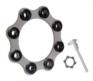
Disc couplings handle misalignment by deflection of the flexible discs. The discs are bolted on a set bolt circle diameter, being fastened alternately to the “driving” and “driven” flanges. The deflection takes the form of a bending/twisting of the link between the adjacent bolts.
In practice, a single flexible disc will only accommodate axial and angular misalignments. Radial misalignments are accommodated by using two flexing discs. The radial misalignment is the total amount of radial displacement divided by the distance between the centers of the flexing discs. Since the disc coupling only identifies radial misalignment as an angular misalignment at each flexing disc, any angular and radial misalignment must be evaluated as a “combined angular/parallel” misalignment.
Since the level of acceptable misalignment is stress related, there is an effect due to both the torque being transmitted and the rotational speed of the coupling. The axial thrust generated in a disc coupling under axial misalignment is related to the bolting arrangement of the coupling. It’s also influenced by the speed of operation and, being of a non-linear stiffness, is dependent on the actual axial deflection experienced.
When the axial growth of machinery shafts during operation is known, it’s acceptable to introduce an axial predilection to the coupling. This involves adjusting the length of the coupling components between the flexing elements so they are “pre-stretched” or “pre-compressed” on installation to an amount that compensates for the known axial growth. This permits the coupling to run at its neutral position during operation.
Kevin Remack
Related Articles

Understanding Shaft Alignment: Basics
Preheater Points Out the Value of Cooling Off
The Trouble with Torque in Electrical Connections

The Cost of Producing Electricity

Installations and Inspections of Corner-grounded Systems

Developing Marketable Engineering Skills