Eliminating Conveyor Concerns
Flexible Steel Lacing Company
Importance of Conveyors
It’s hard to imagine belt conveyors anywhere playing a more important role than at South Africa’s Kendal Power Station. Here, the world’s largest black-coal-fired electrical generating complex converts up to 1.4 million tons a month into more than 4100 megawatts, enough to supply three cities the size of nearby greater Johannesburg.
Coal streams in on twin overland conveyor lines directly from Khutala mine, in the Bombardie Cologne coalfield about 5.75 beltline km (3.6 mi) to the south. At the other end of the powerplant, a monthly ashflow of up to 540,000 tons streams out on another twin conveyor system, heading for a landfill site about 1.5km (.9 mi) away.
While downtime is an unwelcome visitor in any conveyor system, here it threatened to be quite costly by either choking off electrical output or demanding emergency handling of ash that keeps coming regardless of whether a conveyor is there to take it away. Perhaps the biggest problem plaguing Kendal’s conveyors at both ends — frequent shutdowns due to belt slippage — was virtually eliminated when plant engineers discovered the magic of ceramic-tile drive pulley lagging.
Eleven years in construction, Kendal was officially opened in October, 1994, as a state-of-the-art facility and largest of 24 power stations owned by government-controlled Eskom, which together produce 95% of South Africa’s electrical power and more than half of all power generated throughout the continent. Aside from its impressive size and output, Kendal Power Station also captured the attention of the electrical power industry as the world’s largest producer to use indirect dry cooling. This technology was pioneered by Eskom to maximize conservation of water, which already was in limited supply across the Mpumalanga Province.
Rising abruptly from relatively flat savanna, where herds of zebra and springbok pay it little attention, Kendal Station carves a striking skyline with a lineup of six rectangular boiler houses around 100m (328′) tall, flanked by six venturi-type cooling towers, three at each end of the boilerhouse row. These towers rank as the world’s largest, measuring 165m (541′) high and the same across their base diameter. Commanding the center of all this are two chimneys reaching heights of 275m (902′). Almost hidden amidst these giants is Kendal’s 526m (1,726′)-long turbine hall, where the boiler steam does its work.
Coal Concerns
Nearby to the south lies the plant’s Coal Stockyard (CSY), a 1,200 x 1,000m (3,937 x 3,280′) rectangle designed to hold up to 3.25 million tons. Coal crushed to -38mm (1?”) at the mine comes to the CSY on two parallel overland conveyor lines, each an end-to-end series of four belts. Both coal streams pass through the central area of the CSY on two parallel conveyor lines spread 150m (492′) apart. During normal plant operation, the coal usually continues across the CSY on its way to the powerplant.
At various times, some of the coal is diverted by two mobile bucketwheel stacker/reclaimers, which roam the central CSY belts maintaining “live” piles between the two beltlines. Six live piles — three for each machine — together total about 250,000 tons. These piles are routinely reclaimed in rotation, each one usually within a week, to feed the powerplant during early morning or weekend hours when the mine is not coaling. Two larger areas outside the beltlines — totaling roughly 80% of the CSY footprint — each hold “seasonal” piles of 1.5 million tons. There, the coal is compacted to prevent fires, monitored by infra-red thermographics, and held in reserve for emergencies.
Upon leaving the CSY, the two conveyor lines regroup and continue side-by-side along another series of three belts each, leading into a warren of 25 conveyors called the Terrace System. Here the coal stream is split up and distributed to thirty 1,000-ton bunkers — five serving each boiler — maintaining an immediate supply that can support eight hours of electrical generation at full load. Each bunker feeds a dedicated pulverizing mill, which reduces the coal to powder for injection into the burners.
Khutala’s coal is bituminous, with sulphur content of <1%, carbon content of 41%, and ash content of 33%. After burning, 99.99% of the resultant fly ash is recaptured by electrostatic precipitators aided by sulphur trioxide (SO3) injection. The ash is processed to minimize dusting, then reunited with the coarse ash that dropped out below the boilers, creating a combined waste stream of up to 18,000 tons per day. This stream moves out to the ash dump on two conveyor lines each comprising four long belts and nine short ones. Its destination is a pair of ash stacker cranes that creep around on tank-like continuous treads to spread their deposits. Ultimately, the fully filled areas they leave behind are covered with topsoil and regrassed.
In total, from mine to landfill, Kendal Power Station depends on 61 individual belts ranging from 22 to 2,035m (72 to 6,676′) long, center to center, and 1,250 to 2,100mm (49-83″) wide, carrying up to 4,100 tph at speeds from 0.75 to 4.9m (2?-16′) per second.
Avoiding Slippage Shutdowns
According to Coal Plant Senior Engineer Dennis Child, both coal and ash ends of the system have long suffered the problems of belt shutdowns or damage due to pulley slippage. “We had slippage incidents in the CSY at least four times a week during the rainy season,” he recalls, noting that downpours here can drop 50mm (2″) in half an hour. “Between rains, slippage was fairly normal in early morning when the dew is heavy and we’re reclaiming wet coal off the stockpile. But even in normal dry weather, we’d be stopped by load-related slippage perhaps six times a month. In worst cases, we’ve had rubber-lagged pulleys chew the bottom cover off the belt down to the cords. We’ve had to replace large sections of belt due to such damage — in one period as much as 40 metres (131′) — at costs that range from R800 to R1,400 per metre. Often the pulley lagging needed replacement as well.”
While only one belt line from the mine through the CSY can sustain the powerplant’s needs, he points out, one line alone cannot bring in enough surplus to also replenish the live piles on schedule. In addition, having one conveyor line down along that part of the system sets mine production back irreplaceably, because storage capacity at the mine is minimal.
“In the Terrace,” he notes, “one beltline can easily move enough coal to satisfy all six boilers. However, slippage problems once stopped both initial incline conveyors — the two that bring incoming coal up to the three Terrace Bins to begin distribution. When the Terrace is unable to supply enough coal, power production could be affected. If that were to result in shutting down any boilers, the loss of generating revenue plus the fuel-oil cost to restart the boilers could run into the millions (Rand).”
Capacity Increase Raises Tensions
Slippage problems threatened to become worse when, in 1998, work began on a plan to increase the coal plant’s design capacity by about 15% to 15.2 million tons per year. A design review showed that this would require an approximate 50% speedup in the first three belts along both overland lines from the mine to the CSY. This in turn called for greater belt tension to provide the higher pulley traction needed to pull the belt load faster. Tension mass in the gravity take-ups would be increased by at least 45%. Subsequent belts in the coal stream were wide enough to accept greater loads without any increase in speed…but they still would need their tensions increased to accommodate heavier loading.
Kendal engineers then discovered that the take-up towers used on four belts in the coal stream would not be strong enough to accept the added weight needed to increase belt tension, and would have to be rebuilt. Tower take-ups originally were installed as a design solution to space constraints, Child explains, and no alternative design was considered practical here.
Noting the results of ceramic pulley lagging tried at one of Eskom’s other power stations earlier, they suspected that adding ceramic lagging might achieve the needed increase in pulley traction without requiring more tension weight.
“We investigated several options,” Child recalls, “including ceramic tiles bonded directly to the drum and ceramic-epoxy paste applied directly to the drum, but considered these a bit risky for our application. With the levels of belt tension common here, we feared that the rigidity of direct-bonded tiles might damage the belt, and that drum deflection would dislodge the tiles. An added concern with the paste alternative was vibration at high speeds, as we felt it would be very difficult to assure that the paste layer would be truly concentric to the drum surface. This brought us to conclude that ceramic tile set in rubber backing would serve our needs best, as its resilience would withstand drum deflection and avoid belt damage, while its consistent thickness would prevent eccentric vibrations.”
Ceramic Lagging Solves Problem
With that conclusion,” he continues, “we set up a test on a pair of relatively short-cycle conveyor segments we call CS2A and B.” As the first conveyors to start coal moving toward the Terrace from the CSY, he notes, these are 1,800mm (71″) wide belts, 130m (426′) long c-to-c, designed to move 2,665 tph at 2.5m (8.2′) per sec. in support of the capacity upgrade. “We were surprised to see that ceramic lagging allowed us to reduce the tension mass by 46% and still eliminate slippage trips,” he reports.
Through November of 1998, ceramic lagging was added to eight more conveyors leading up to and out of the CSY, including those involved in the speed upgrade, allowing tension mass reductions ranging from 16% to 73% while virtually ending trips due to slippage.
By that time, one particularly troublesome conveyor in the Ash Plant was singled out to try ceramic lagging as well. In the Ash Plant, Childs explains, belts were fewer but problems were worse. In contrast to the Coal Plant belts, most of which are cladded for protection from the elements, Ash Plant belts are mostly exposed to the environment. With trips averaging about 70 per month, largely due to rain-induced slippage, belt availability was down around 65%.
When an ash belt goes down, ash starts piling up at a rate of about 1,000 tph. “At one point,” Child says, “we were paying outside contractors to truck about 30,000 tons per month to the landfill at the rate of R6/ton. It became so routine that we set up an emergency ash dump with a special conveyor to reload the dumped ash back onto the overland conveyor, using a front-end loader to clean up the dump at R300/hour…but even that could cost R150,000 per month.”
The conveyor targeted for ceramic lagging was an extendible unit that alone was largely responsible for the plant’s low availability. This unit transfers ash from an overland conveyor across 100 to 180m (328-590′) to a “shiftable” conveyor that feeds one of the mobile landfill stackers. “We had endless problems with this conveyor tripping for various reasons,” Child recalls. “To reduce slippage, maintenance crews tried using the extendible electric tensioning winch to increase belt tension, ultimately by about 70%. The rubber drive pulley lagging burnt to the cover of the belt, winding it up to about three times the normal diameter of the pulley and snapping the belt.”
Spreadsheet Comparison Revealing
From the preceding months of experience with ceramic lagging in the Coal Plant, Child had developed a detailed spreadsheet comparing three designs of ceramic-tile-in-rubber lagging. While they were very much alike in many ways, they differed in a few criteria that he considered important for future specification. Most notably, these were % of pulley circumference tiled, adhesive strength in three key areas and “safe edge” distance.
The first criterion primarily reflects whether the tiles are in single or double rows, and the spacing between rows, as tile dimensions are quite similar if not identical. “Among the three designs, these differences can result in tile coverage varying from around 65% to more than 80% of pulley circumference,” he explains. “When I specify lagging, I convert the number of rows around the circumference of the pulley into Rand value. I also consider the percent coverage of ceramic around the circumference, because it’s the ceramics we are paying for rather than the rubber backing.”
Adhesive strength was measured in terms of pullout force required, by an independent testing agency. Tile-to-rubber strength, arguably the most important, ranges from 12N/mm to 18N/mm across the three designs. Rubber-to-metal (pulley surface) ranges from 11N/mm to 15N/mm, and rubber-to-rubber from 6N/mm to 8.5N/mm. Rubber-to-rubber strength — the bond between adjacent strips of lagging — is important for barring contamination through those seams.
“Safe edge” distance is Kendal’s term for the distance between the outer edge of the tile rows and the outer edge of the rubber backing, which was found to vary from zero to 100mm (3.9″) “In our application,” Childs says, “we found at least 50mm (2″) of safe edge desirable because less to none invites trouble when rigging a pulley, either damaging the sling or breaking tiles. Besides that, belts rarely extend out to the full width of the pulley, so any tile in that area is wasted cost.”
Finding the Best Value
“Considering the criteria developed in our comparison,” he continues, “we realized that while the ceramic lagging used in our initial installations was of a lower cost, it was not our best value, so for the Ash Plant problem we specified Flexco’s Flex-Lag?, which had come out at the top of our comparisons.”
Flex-Lag covers the drive pulley faces with 20mm (¾”) square tiles made of high-grade alumina ceramic, molded into flame-resistant rubber backing, which is bonded to the drum in strips. Each tile is embossed with 13 small raised “buttons”, which embed into the belt’s bottom cover to boost traction. Shallow enough to avoid damaging the bottom cover, they counteract the decline of traction that often results as a belt’s bottom cover becomes harder and slicker with age. Flex-Lag ceramic provides 2? times the traction of grooved rubber lagging under wet/muddy conditions and 1?-2 times the traction when the system is dry. The combined thickness of ceramic tiles and rubber backing is less than 12mm (1/2″), but with their characteristic high resistance to wear, ceramic tiles far outlast standard rubber lagging.
“After installing Flex-Lag in the Ash Plant extendible,” Child says, “we were able to relax that belt’s tension from its original 44kN down to an almost unbelievable 8kN. While that belt still can trip on things like belt skew, overloads, DC failures and undervoltages, pulley slippage has ceased to be a problem, so we’ve reduced trips there by more than half.”
From then through June, 2000, as budgets permitted, Flex-Lag was added to 12 more Ash Plant belt pulleys — four of which are on belts with tower take-ups. In that year’s second half, another 14 drives were Flex-Lagged on the coal side, including those on six 13° incline belts in the Terrace System, where Child generally was able to remove a ton of tension weight across the lot. During early 2002, Flex-Lag was added to drive pulleys on the intermediate and boom belts of both stacker/reclaimers.
Long-Term Savings Projected
Originally, Child continues, all of Kendal’s drive pulleys were installed with diamond-pattern rubber lagging. Because rubber drive lagging typically lasted only 8 to 10 months in the Coal Plant, but had much longer life in the Ash Plant, about 95% of re-lagging activity was focused on coal belts.
To evaluate the potential payback of converting from rubber to ceramic in both plants, Child charted 40-year cost projections for both types of lagging on the Coal Plant’s longest overland belt (with tandem drive) and on the Ash Plant extendible. “Although the cost of new rubber lagging is only about 10% of ceramic cost,” he reports, “the significantly longer service life of ceramic soon projects a savings on the coal belt, with the cumulative cost of rubber lagging ending up about 2.5 times greater than ceramic 40 years out. On the ash belt projection, where rubber lagging lasts longer, the lower cost of rubber takes about 9 years to catch up with ceramic, but then continues to climb to a 55% premium over ceramic by the end of the projection. The benefit over time is pretty obvious, and the fact that we don’t have to re-lag Coal Plant pulleys every 8 to 10 months is a bonus.”
“Although we built our projections assuming replacement of ceramic lagging at certain intervals,” he admits, “we don’t actually know how long it will last because none of our ceramic- lagged pulleys have had a failure yet. Considering how little wear is evident, I’m wondering whether we’ll ever have to replace it.”
“I also expect that lower belt tensions resulting from the ceramic lagging will give us substantial savings over time among other critical conveyor components such as gearboxes, couplings and bearings. We initially projected pulley life around 20 years, but with ceramic lagging and 50% lower belt tension, I feel we could increase that by another 10 years.”
Related Articles

Why Machine Learning and AI Are the Future of Oil Analysis
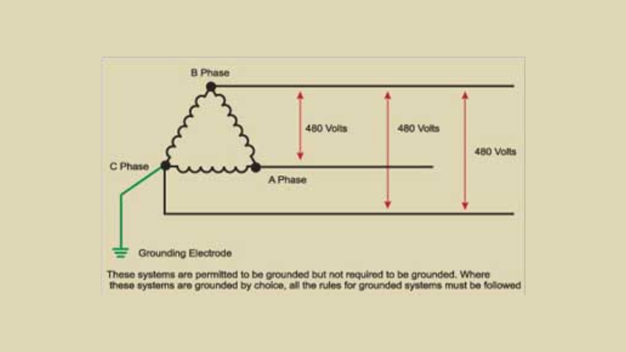
Installations and Inspections of Corner-grounded Systems

The Full Circle of Engineering Education
Solar Engineering FAQ: Harnessing the Power of the Sun
Some Plain Talk About Nuts and Bolts: Part 1 of 2