The Dual Seal Arrangement
www.mcnallyinstitute.com
Dual seals are recommended for a variety of purposes that include:
- To prevent a costly product from leaking
- To prevent a dangerous product from leaking to the atmosphere
- To prevent a pollutant from escaping to the atmosphere
- As a back up seal to prevent costly down time when the first seal wears out or fails. This is an important element in any predictive maintenance program.
All of the above are sensible reasons for using two seals in a pump, but in this paper we will be considering the use of dual seals as an environmental control to prevent the sealed product from either opening the seal faces, or damaging one of the seal components, the two reasons any mechanical seal ever failed.
We can use the dual seals to:
- Control the temperature at a seal face
- Prevent a pressure drop across a seal face
- Eliminate atmospheric conditions outboard of a mechanical seal
- To break down the pressure in a high pressure application, by inserting an intermediate pressure between the seals. Two lower pressure seals can then be used to seal a high pressure fluid that would normally require a very expensive high pressure mechanical seal.
- To provide a lubricant if one is needed to prevent “slip stick”. This is almost always the case when you are sealing a gas.
A dual seal can be of either the rotating or stationary version and can be installed in four different configurations.
- Back to back or facing in opposite directions
- Tandem or facing in the same direction
- Face to face or facing towards each other
- Concentric or one inside the other
The fluid that circulates between the dual seals is called barrier fluid if it is higher than stuffing box pressure. It is called buffer fluid if it is lower than stuffing box pressure. It can be circulated between the two seals by:
- Natural convection using a convection tank. Insulated piping coming from the top of the gland to the convection tank, and finned piping coming out of the tank will aid convection if heat removal is a problem.
- A pumping ring can be installed between the seals for those instances where natural convection is not sufficient to remove the heat being generated between the faces. This is very necessary when oil is used as the barrier fluid. Oil has a low specific heat and poor conductivity, making it a poor choice as a barrier fluid. Most of the newer cartridge dual seals come equipped with a built in pumping ring.
- Introducing the fluid between the seals, from an external source. Be sure to bring the fluid in at the bottom of the gland and out the top to prevent an air pocket from forming in the gland.
The following illustrations describe the rotating version (the spring or springs rotate with the shaft) of these dual seal configurations. You should be aware that a stationary version is also available from any of the major seal companies. You should also consider:
- Use only the hydraulically balanced version of these dual seals to prevent the generation of excessive heat between the seal faces.
- Two way balance is always desirable in any dual seal application to allow you the option of using either a high or low pressure barrier fluid and to prevent the seal faces from opening if either the system or the barrier fluid pressure fluctuates.
- Be sure to select seal faces with good thermal conductivity.
- Try to locate any elastomers away from the seal faces if possible. Elastomers are very sensitive to heat.
First we will look at the back to back version of a rotating seal:
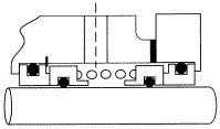
The rotating back to back version would be your worst possible choice. Here are some of the reasons:
- This configuration requires a higher barrier fluid pressure between the seals. This means that an inner seal leak will cause a dilution of your product. There will be no visible evidence of this happening unless someone notices a change in the product concentration or tank level.
- In operation the outboard seal is carrying the higher differential pressure and should be the first seal to wear out or fail. When this occurs the barrier fluid pressure will drop and the inner seal can blow open. In other words, if the seal works as designed, both seals will fail at the same time.
- High barrier fluid pressures are hard to maintain because of pressure fluctuations and varying system pressures. Water hammer and pressure surges are not that uncommon.
- A reversing pressure can blow the inner seal open. Seals should shut with pressure. They should not “blow open” when something goes wrong.
- If a connection in the barrier fluid system is ruptured the inner seal can blow open, dumping the pump contents to the environment. The second seal would be of no use.
- Note the snap ring holding the inner stationary face against the end of the stuffing box. This part is missing in just about every application I have ever seen. Without this snap ring, higher process fluid pressure can over compress the inner seal spring force moving the stationary face into the rotating face, causing massive face wear and very high rubbing temperatures.
- A common version of this seal utilizes spring loaded dynamic O-rings. O-rings should be placed in O-ring grooves, they should not be spring loaded. The Durametallic CRO seal is typical of that configuration.
- This version is known as the “double fretter” in the sealing industry. It will groove the shaft in two places just beneath the O-rings. See another section of this series for a further explanation of shaft fretting.
- This seal is often used in slurry applications. Centrifugal force will throw the slurry into the inner faces causing excessive carbon wear. The slurry will then pack in front of the moveable face preventing it from moving as it tries to slide forward to compensate for normal face wear, thermal growth, most impeller adjustment and shaft end play.
Tandem is the next version. This is the configuration you find in most Oil Refinery applications.

Here are a few comments about this version:
- It takes the most axial space of the four types and as a result is seldom found in the process industry, although newer designs are being made shorter as a result of computer finite analysis programs.
- You need two glands and this adds to the cost as well as the axial space required
- A low pressure buffer fluid is circulated between the seals, eliminating the possibility of product dilution.
- A loss of buffer fluid will not cause the seal faces to open
The face to face version is next
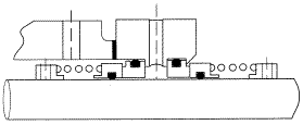
This face to face version is a compromise between the “back to back” and the tandem version:
- You normally run a lower pressure buffer fluid between the faces. If you lose this pressure the seal faces do not open.
- Half the seal is in the stuffing box with the other half outside. This means the seal does not take an excessive amount of either axial or radial space.
- Many versions of this seal specify a common stationary unit with holes drilled in the stationary for circulation. I do not like this configuration because if you break the stationary face you could lose both seals. There should be two separate faces specified for maximum safety.
The concentric version is next, but I do not have an illustration to show you. In this version we have one of the seals inside the other sharing a common stationary face. The stationary face is drilled between the rotating faces to allow circulation of the barrier fluid.
- Like the tandem and “face to face” versions you normally circulate a low pressure buffer fluid between the faces.
- This configuration takes the least amount of axial space, but requires the most amount of radial space. You will sometimes find them used on a top entering mixer application, but you will seldom find them in a pump application because of the radial space required.
- Because of the common stationary used there is the danger of losing both seals if you break the stationary face.
The convection tank is a unit you can either purchase or manufacture your self. When a manufacturer supplies this unit, it requires a “Boiler Maker Stamp” and a 600 psi rating, making it very expensive to purchase. You can probably manufacture one for your purposes at a much lower cost.
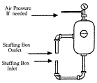
You have many choices when it comes to your choice of the buffer or barrier fluid:
- Anti-freeze is popular in northern climates. Do not use the commercial brand that contain a chemical used to plug leaks in radiator hoses.
- Finished product is always acceptable.
- A fluid compatible with your product is often used.
- You might consider a cleaner or solvent that will be used to clean the system.
- If a flush is being used in the system you can always use that as a barrier fluid.
- Once again, try to avoid using any type of mineral, petroleum or vegetable oil as a barrier fluid. Oil has a low specific heat and poor conductivity that can cause varnishing and coking problems between the seals. Some of the newer synthetic and heat transfer oils can be used if the temperate is not too high.
Now that you have all of the basics under control, we will use a dual seal to solve some of our common application problems:
Use a pressure higher than stuffing box pressure between the seals to:
- Prevent kaolin (china clay) or other micron size solids from penetrating between the faces.
- To provide face lubrication if the product you are sealing is a non lubricant. This will prevent excessive wear and “slip-stick” problems.
- To prevent a pressure drop across the faces that could:
- Cause a product to vaporize and open the lapped faces
- Cause a fluid to solidify, paint is a good example
- Cause Ethylene Oxide to attack the dynamic O-ring in the inboard seal. Ethylene Oxide can penetrate the elastomer and blow out the other side if there is a differential pressure across the O-ring.
Use a lower pressure between the seals to:
- Create an intermediate pressure in a high pressure application.
- Use a low pressure, with an anti-freeze as barrier fluid, to prevent ice from forming outboard of the seal when sealing products that freeze at atmospheric pressure. You will see ice on the outside of the pump if you trying to seal one of these applications.
- To be able to identify which seal has failed.
CAUTION Do not split the pressure between stuffing box and atmospheric pressure. This will put an equal load on both seals and they will wear out at the same rate.
Circulate the correct temperature fluid between the seals, especially when the pump is shut down. You are going to have to make the decision as to what barrier fluid temperature is needed. You can increase the temperature, decrease it or hold it within narrow limits:
- To prevent a product from crystallizing
- To prevent a product from vaporizing
- To prevent a product from becoming viscous
- To prevent a product from solidifying
- To prevent a product from building a film on the seal faces
- To prevent the product corrosion rate from increasing with heat
Here are a few more considerations:
- With the proper selection of barrier or buffer fluid pressure you can transfer the hydraulic load to either the inboard or outboard seal. It is never wise to use the barrier fluid at a pressure of half the stuffing box pressure because this would cause both seals to share the load and they would be expected to wear out at the same time. It is always better to select one of the seals to carry the load.
- A transmitter can be installed on the convection tank that will send a signal to a control panel informing the operator which seal has failed or worn out.
- Some people are tempted to run the outboard seal dry. With the correct selection of the seal type and the proper materials this is possible, but not recommended. You should use a convection tank under some fluid pressure to be able to tell if you have had a seal failure, and which seal has failed.
- Use the cartridge version of these seals to ease the installation problem and allow you to make impeller adjustments and compensate for thermal shaft growth. Be sure the cartridge sleeve is sealed to the shaft inside the stuffing box, or fluid will flow between the cartridge and the shaft making cartridge removal difficult. Some manufacturers seal on the outboard end, but this is not desirable.
- If you use the stationary version of these seals:
- Back to back is acceptable, the fluid will be at the seal O.D.
- Tandem is acceptable if the stationary units are positioned in the glands.
- Face to face is not acceptable. The fluid will be at the I.D. of the faces and centrifugal force will work against you.
- Concentric is O.K. if you can locate a concentric version of a dual seal.
- If you are going to use a cartridge version of the stationary dual seal, be sure it has some type of self aligning feature to prevent excessive movement as a result of “cocking” when the cartridge sleeve is attached to the shaft.
Related Articles

OEE: Overall Equipment Effectiveness
What the Pump Was Designed to Do and Why it Doesn't Do it
What is Wrong with the Modern Centrifugal Pump?

Digging Up Savings: Go with the Flow
Chain Drive Design Recommendations

Classifying Chemicals to Assure Effective Sealing
