Pneumatic Power Circuits
Pneumatic directional control valves and cylinders are most commonly used in power circuits, with the valves controlling cylinders that, in turn, provide work. As we learn about a few of these circuits, other accessory valves will be introduced, along with some interesting ways of using them.
The directional control valve in any power circuit should be mounted as close as possible to the cylinder it controls. Pressure drops in long hoses leading to the cylinder may cause the piston to move too slowly. Also, long hoses between the valve and cylinder may contain more air volume than the cylinder will accommodate, thus the lubricated air might never reach the cylinder before it is fully extended. On the return stroke, the lubricated air is exhausted back through the valve to atmosphere.
Short hoses between the valve and cylinder will help to solve both of these problems, but if using one is not possible, try a quick exhaust valve mounted close to the cylinder.
A quick exhaust valve is actually two check valves with a common poppet or ball which allows incoming air to be ported to the cylinder and exhausting air from the cylinder to be dumped directly to the atmosphere. The resulting decrease in back pressure causes the cylinder to travel much faster. It also eliminates the reverse displacement of incoming lubricated air by the exhaust in the connecting hoses, allowing the cylinders to be lubricated (figure 1).
A decelerating device, preferably mounted outside the cylinder, should always be used with a quick exhaust. This may be a positive stop protected by a urethane bumper pad, a hydraulic dashpot, or at the very least, an internal cylinder cushion.
The acceleration of any pneumatic cylinder is generally accomplished as fast as the balancing forces in the cylinder will allow it to happen. Very seldom will the forces within the cylinder during acceleration exceed the design limitations of the cylinder.
Deceleration, however, is another story. If the combined inertia of the load and the moving cylinder parts is stopped by the cylinder reaching the end of its stroke, the design limitations of the cylinder will most often be exceeded and cylinder damage will result.
End-of-stroke cushions which trap and compress the air just before the end of the piston travel are only designed to change a “crash” into a “boom.” They will seldom solve a load inertia problem. Always try to absorb the inertia by stopping the load with a deceleration device outside of the cylinder.
Slowing the cylinder to a controllable level is generally accomplished by restricting the flow of compressed air into or out of the cylinder. The least expensive way of accomplishing this is to use a four-way, five-port control valve with a needle valve installed in each of the exhaust ports (figure 2). This will effectively give you a “meter-out” control, with the exhaust restricted and the air flow entering the cylinder unrestricted.
A better method of slowing the cylinder is to use flow control valves directly connected to the cylinder ports to restrict the exhausting air only. Flow control valves are a combination of an adjustable needle valve controlling the flow in one direction and a check valve to allow the full flow bypass of air around the needle valve in the other direction.
Varying frictional forces in the cylinder and the machine may cause jerky or erratic cylinder motion, especially at low speeds. Using flow controls in a meter-in direction will accentuate the problem due to the slow, uncontrollable buildup of air pressure behind the piston.
A meter-out flow control, which restricts the exhausting air, will cause the incoming air pushing the cylinder to build to full pressure, minimizing the small frictional fluctuations, thus reducing the tendency for jerky motion (figure 3). When in doubt, meter out. However, for extremely slow-moving applications, an additional self-contained hydraulic speed control unit is required.
Hydraulic speed controls will accurately control a slow pneumatic cylinder feed — usually in one direction only. This is a requirement in many pneumatically fed machining operations such as drilling or milling applications and cut-off saw feeds. Hydra-checks, as these units are sometimes called, are self-contained hydraulic cylinders with internally piped circuitry to control the passage of oil from one side of the cylinder to the other.
A similar device can also be constructed by using a tandem cylinder (figure 4) with the back piston being driven with pneumatic power and the front piston fitted with a bypass circuit for the oil using a flow control and a suitable make-up reservoir on the non-pressurized side of the flow control. MRO
Ted Grove is corporate training manager for Wainbee Limited, Mississauga, Ont., and a widely experienced fluid power trainer.
Click here to read more about the Costs and Capabilities of Pneumatic, Electric Actuators
Related Articles
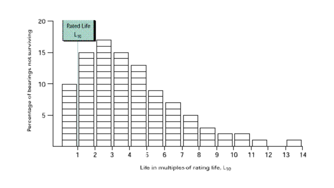
Bearing life is defined as the length of time, or the number of revolutions, until a fatigue spall of a specific size develops. This spall size, regardless of the size of the bearing, is defined by an area of 0.01 inch2 (6 mm2). This life depends on many different factors such as loading, speed, lubrication, fitting, setting, operating temperature, contamination, maintenance, plus many other environmental factors. Due to all these factors, the life of an individual bearing is impossible to predict precisely.
Bearing life is defined as the length of time, or the number of revolutions, until a fatigue spall of a specific size develops. This spall size, regardless of the size of the bearing, is defined by an area of 0.01 inch2 (6 mm2). This life depends on many different factors such as loading, speed, lubrication, fitting, setting, operating temperature, contamination, maintenance, plus many other environmental factors. Due to all these factors, the life of an individual bearing is impossible to predict precisely.
See More
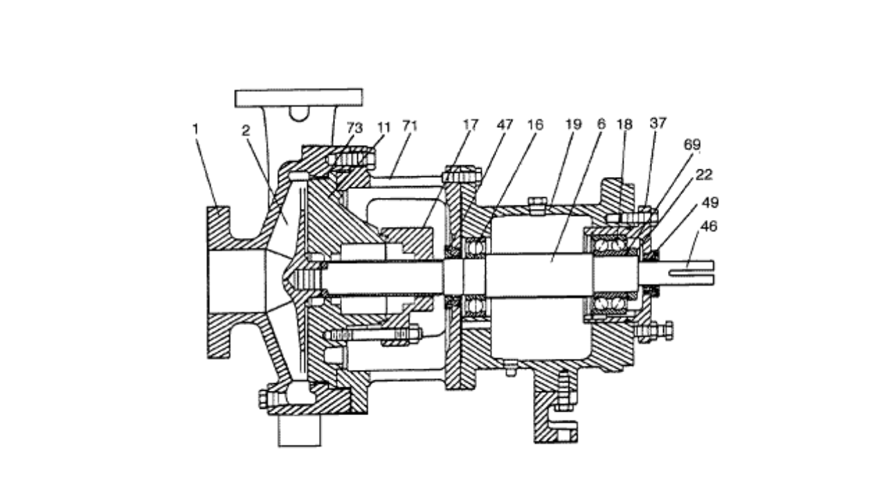
Ask for a modern centrifugal pump recommendation from your favorite supplier and chances are he will recommend one of the standard pump designs that conform to either the A.N.S.I., I.S.O. or D.I.N. specifications. On the surface that might seem like a good recommendation, but the fact is that all of these designs will cause you maintenance problems. Refer to the illustration prior to diving into the details of the obvious problems found within these designs.
Ask for a modern centrifugal pump recommendation from your favorite supplier and chances are he will recommend one of the standard pump designs that conform to either the A.N.S.I., I.S.O. or D.I.N. specifications. On the surface that might seem like a good recommendation, but the fact is that all of these designs will cause you maintenance problems. Refer to the illustration prior to diving into the details of the obvious problems found within these designs.
See More
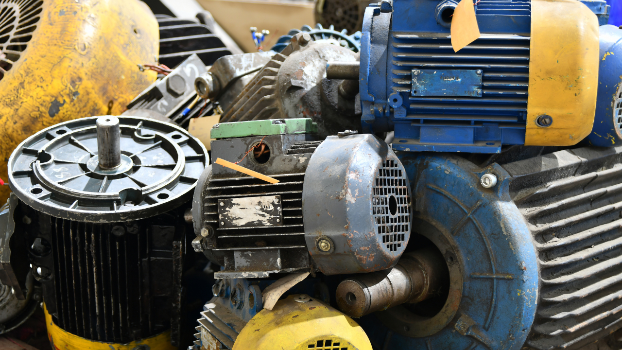
The following charts will give you multiple pathways to assist when you are attempting to troubleshoot AC Motors. The 4 problems covered are: Problem A - Motor won't start or motor accelerates too slowly, Problem B - Motor runs noisy, Problem C - Motor overheats, Problem D - Motor bearings run hot or noisy
The following charts will give you multiple pathways to assist when you are attempting to troubleshoot AC Motors. The 4 problems covered are: Problem A - Motor won't start or motor accelerates too slowly, Problem B - Motor runs noisy, Problem C - Motor overheats, Problem D - Motor bearings run hot or noisy
See More
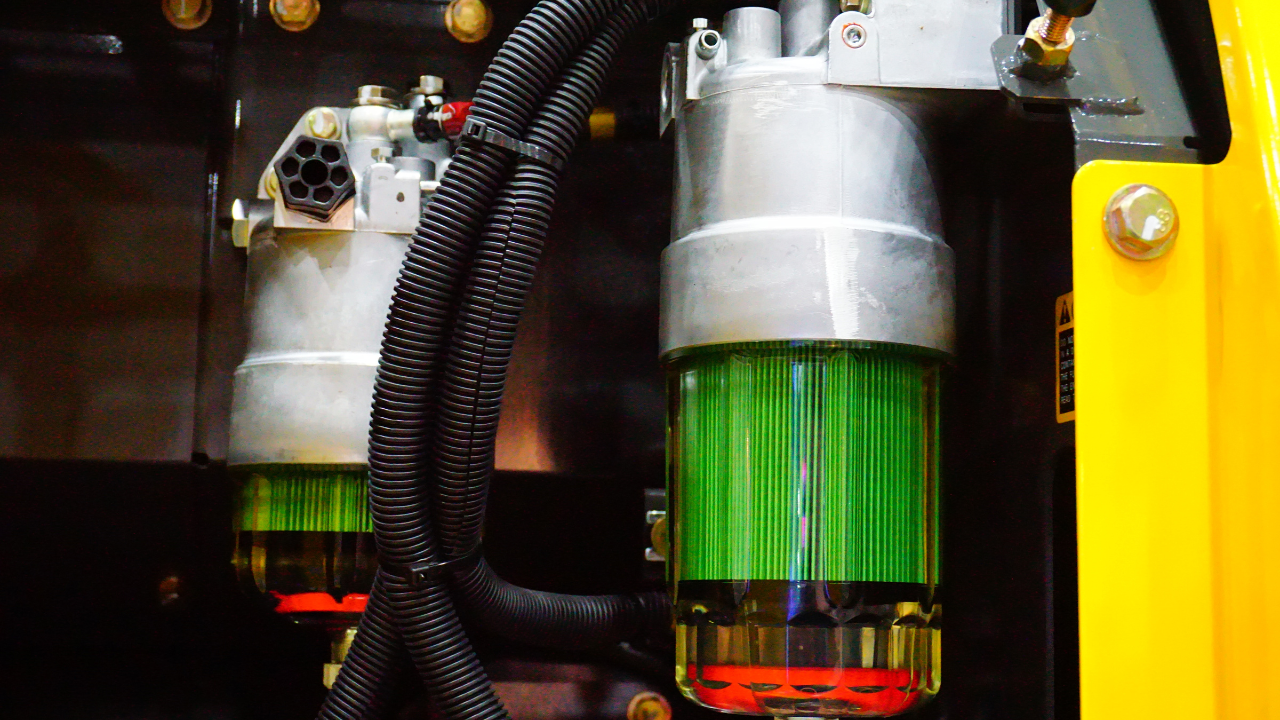
Given that particle contamination of hydraulic fluid reduces the service life of hydraulic components, it would seem logical that a system can never have too many hydraulic filters. Well... not exactly. Some hydraulic filters can actually do more harm than good and therefore their inclusion in a hydraulic system is sometimes misguided.
Given that particle contamination of hydraulic fluid reduces the service life of hydraulic components, it would seem logical that a system can never have too many hydraulic filters. Well... not exactly. Some hydraulic filters can actually do more harm than good and therefore their inclusion in a hydraulic system is sometimes misguided.
See More
I often hear the words “relays” and “contactors” used seemingly interchangeably, but there must be a technical difference, right? So, I took a quick trip to Rexel Automation Solutions in Salisbury, MD to meet with Nate Titus, Account Manager, and get the skinny on these beloved but sometimes pesky industrial workhorses.
I often hear the words “relays” and “contactors” used seemingly interchangeably, but there must be a technical difference, right? So, I took a quick trip to Rexel Automation Solutions in Salisbury, MD to meet with Nate Titus, Account Manager, and get the skinny on these beloved but sometimes pesky industrial workhorses.
See More
This article covers the two main plant numbering systems that together form the framework on which all maintenance programmes are based and describes the value that can be created by integrating these identification systems. These two systems are: Equipment Numbers, or more accurately, Equipment Location Numbers Stock-Keeping Unit (SKU) numbers or, preferably, Material Catalogue Numbers. A third, less critical but still important numbering system for Stores location (or “bin”) numbers, is also included.
This article covers the two main plant numbering systems that together form the framework on which all maintenance programmes are based and describes the value that can be created by integrating these identification systems. These two systems are: Equipment Numbers, or more accurately, Equipment Location Numbers Stock-Keeping Unit (SKU) numbers or, preferably, Material Catalogue Numbers. A third, less critical but still important numbering system for Stores location (or “bin”) numbers, is also included.
See More
A pump’s efficiency can degrade as much as 10% to 25% before it is replaced, according to a study of industrial facilities commissioned by the U.S. Department of Energy (DOE), and efficiencies of 50% to 60% or lower are quite common. However, because these inefficiencies are not readily apparent, opportunities to save energy by repairing or replacing components and optimizing systems are often overlooked.
A pump’s efficiency can degrade as much as 10% to 25% before it is replaced, according to a study of industrial facilities commissioned by the U.S. Department of Energy (DOE), and efficiencies of 50% to 60% or lower are quite common. However, because these inefficiencies are not readily apparent, opportunities to save energy by repairing or replacing components and optimizing systems are often overlooked.
See More