Analyzing Mechanical Systems Using Infrared Thermal Imaging
www.petersonpredict.com
What is Infrared Thermal Imaging
Infrared Thermal Imaging is an excellent condition monitoring tool to assist in the reduction of maintenance costs on mechanical equipment. The technique allows for the monitoring of temperatures and thermal patterns while the equipment is online and running under full load. Most mechanical equipment has allowable operating temperature limits that can be used as guidelines. Unlike many other test methods, Infrared Thermal Imaging can be used on a wide variety of equipment including pumps, motors, bearings, pulleys, fans, drives, conveyors etc. This section will explain the benefits of Infrared Thermal Imaging as a condition monitoring tool for plant mechanical systems.
We will highlight a few uses of Infrared Thermal Imaging when applied to analysis of mechanical equipment.
Infrared Thermal Imaging is an electronic technique that quite literally allows us to see thermal energy. With this new capability plant maintenance personnel have recognized Infrared Thermal Imaging as one of the most versatile and effective condition monitoring tools available today. Infrared Thermal Imaging enhances a company’s ability to predict equipment failure and plan corrective action before a costly shutdown, equipment damage, or personal injury occurs.
Why does Infrared Thermal Imaging Work?
All mechanical systems generate thermal energy during normal operation which allows Infrared Thermal Imaging to evaluate their operating condition. One of the biggest problems in mechanical systems is excessive temperatures. This excessive heat can be generated by friction, cooling degradation, material loss or blockages. An excessive amount of friction can be caused by wear, misalignment, over or under lubrication and misuse.
Since most equipment or processes are designed to eliminate thermal energy under normal operation, simply identifying a thermal pattern does not mean a problem has been located. The thermographer must be familiar with the mechanical components being evaluated. Once a normal thermal signature is obtained and understood, any deviation from this normal signature will then provide evidence of a suspect problem developing.
In mechanical applications, Infrared Thermal Imaging is more useful for locating a problem area than for indicating the root cause of the overheating. The heat is usually produced within a component that is not visible directly to the camera. That heat must conduct up through the material and present itself as a pattern on the surface of the object in order for the infrared camera to sense it. Other equipment such as vibration analysis, oil analysis, and ultrasound can be employed to further determine where the problem actually lies.
Let’s take a look at some of the applications and the benefits derived from finding these with Infrared Thermal Imaging.
Thermography Applications
| APPLICATION | CONDITIONS DETECTED |
| Drives/Conveyors, Pillow Blocks, Couplings, Gears, Power Transmission Belts, Pulleys, Shafts | Overheated bearings or rollers, misalignment of shaft, pulley or coupling, lubrication failure uneven pressure. |
| Motors | Overheating of windings and bearings, blockages in cooling passages, friction, damping, material deformations, brush contact problems, rotors. |
| Pumps/Compressors/Fans/Blowers | Overheated bearings, high compressor discharges temperature, high oil temperature, and broken or defective valve. |
| Internal Combustion Engines | Valve or injector malfunction, blocked radiator tubes and oil coolers. Thermal distribution, high radiator inlet or outlet temperature. |
| Heavy Duty Equipment – Tires, Bearings, Brakes, Hydraulics, Kilns, Ball Mills, Paper Machines | Overheating brakes, tires, bearings, pulleys, gears, gear or pulley misalignment, and blockages in hydraulics. |
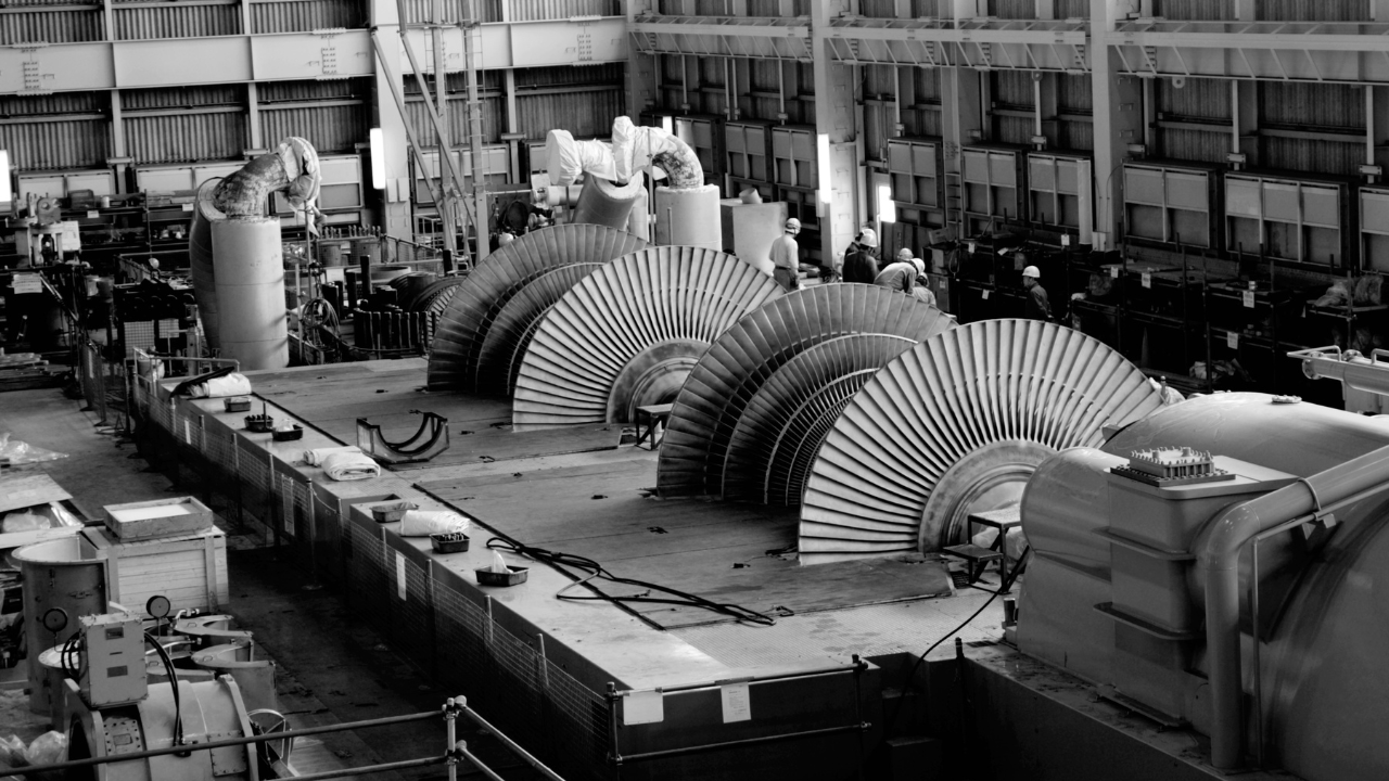
| Mechanical Drive Turbines and Small Turbine Generator Units, Gas Turbine, Exhaust Ducts | High lube oil temperature, high bearing temperatures, faulty stop/control valve operation, uneven metal temperature, leaking shaft seals, gas turbine firing conditions, including deterioration in firing chambers, cross firing tubes. |
| Ovens, Furnaces, Kilns, Pipes | Location and severity of damaged insulation, location of steam leaks in buried steam lines. |
| Valves: Shutoff Valves, Relief Valves, Steam Traps | Leakage, blockage. |
Improved Troubleshooting
Infrared Thermal Imaging definitely should be one of the tools that are selected for motor and rotating equipment inspection. Thermographic examination can help technicians use the other tools, such as vibration analysis, more effectively. If a thermal anomaly is found, then the other tools can be employed to help isolate the cause of the problem.
Motors and Generators
When considering electric motors and generators, operating temperatures and thermal patterns can be a valuable key in a predictive maintenance program. All motors have a normal thermal pattern as well as given maximum operating temperature. This temperature is usually stated on the nameplate of the motor and is normally given as a rise in degrees C above the ambient air temperature. Most motors are designed to operate in ambient temperatures that do not exceed 40 C. Conditions such as inadequate air flow, partial discharge, unbalanced voltage, bearing failure, insulation failure and degradation in the rotor or stator can be identified with an Infrared Thermal Imaging monitoring program. Abnormal thermal patterns can also identify misalignment in couplings when these devices are used in conjunction with motors.
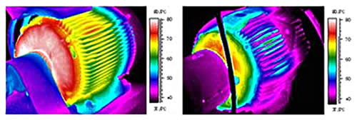
When comparing these two motors, the thermal patterns are similar but there is a marked overal temperature rise on the motor on the left.
Belts and Pulleys
Belts and pulleys are good candidates for Infrared Thermal Imaging inspection. The interaction of the pulley wheel and the belt generates friction as the belt contacts and then leaves the pulley surface. Additionally, the continuous tension and compression of the belt causes internal friction. Both of these processes result in heat being generated which can be seen with the infrared camera. Comparing the thermal patterns of several pulley belt systems can provide clues to improper operation.
The temperature distribution across a pulley sheave should be uniform if everything is working as intended. In one documented case of a pulley arrangement with several belts, several belts were found to be running hotter than others.
The belts were replaced with no improvement in the thermal distribution. Something was obviously wrong. The pulley did not appear to be worn, yet it was replaced to see if the uneven heating would disappear. To everyone’s surprise the uneven thermal distribution remained. At this point some people were questioning the Infrared Thermal Imaging data!
Pulley-bearing combinations like this can be investigated with Infrared Thermal Imaging.
Vibration testing confirmed there was something amiss. Test data showed that the fan speed was decreasing in relation to the motor speed over a period of time. This means that the belts were slipping. At this point, all the materials that had been removed were carefully inspected. It was then hypothesized that the belts may not have come from a matched set. After checking with the stockroom clerk, it was determined that these belts had not been stored and retained as a matched set. A matched set of belts was procured and fitted to the pulley system, and the Infrared Thermal Imaging showed a nice even thermal distribution. This is an example where Infrared Thermal Imaging used with other instrumentation and the perseverance of the investigators drove the inspection process to a correct and satisfactory resolution of the problem.
Provide Evidence of Proper Installation Bearings
Bearing problems are generally found by a comparison of surface temperatures; comparing one bearing to another working under similar conditions. Overheating conditions are documented as hot spots within the infrared camera and are usually found in comparing equipment to equipment, end bell to end bell (for the same type of bearings) and stator to end bell temperatures (determined by motor design and configuration).
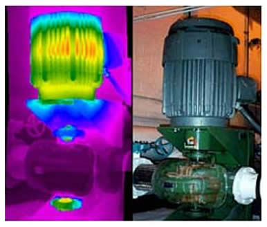
Vertical motor pump combination displaying elevated temperature in lower thrust bearing.
An automotive facility was having continual problems with some of their motor and pump combinations. The bearings of the pumps repeatedly failed. An Infrared Thermal Imaging inspection confirmed that the lower thrust bearing was indeed warmer than the other bearings in the pump. Further investigation revealed that this motor – pump combination was designed to operate in the horizontal position. In order to save floor space, the pump was mounted vertically below the motor. As a result, the lower thrust bearing was overloaded leading to premature failure. A failure like this costs over $15,000 to repair, not counting for lost production time (at this plant an opportunity cost of $30,000 per minute and labor costs over $600 per minute.
Reduce Operating Costs – Leaking or Blocked Pipes and Valves
Steam Traps
Steam is an efficient way to transport heat energy. The latent heat needed to transform water into the gaseous state, steam, is extremely large. This means that large amounts of heat energy can be transported with a minimum temperature differential to the environment. This equates into lower energy and insulation costs.
When steam arrives at the site where heat energy is needed, it condenses, thereby releasing the large latent heat it was carrying. The condensate formed by this process must be removed by the steam system and returned to the boiler where it is turned back into the steam and the cycle is repeated.
The steam trap performs this function; to hold back live steam while allowing gases and condensate to pass through. This allows more energy to be obtained from the steam, thus raising a steam system’s overall efficiency.

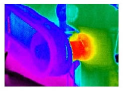
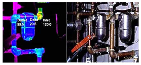
In these two photos of steam traps, the Infrared Thermal Imaging photo on the left shows the point of leakage.
Steam traps, like any mechanical device, eventually fail. Most are designed to fail in the open position to maintain steam system operation. When they fail in the open position, they “blow” live steam. This costs energy dollars which the steam trap was installed to conserve. Occasionally, steam traps fail in the closed position. This causes condensate back up in the steam system with potentially disastrous results.
Thermogram and visible image of a failed inverted bucket steam trap.
Properly performed Infrared Thermal Imaging can identify steam traps that are blowing steam as well as those that may fail closed. Steam traps are sometimes located in inconvenient areas where they are hard to reach using other NDT technologies. This fact makes trap diagnosis by IR especially useful.
In a 100 psig system with production costs of $8/1000 pounds, a ¼”leak will cost $20,0000 in one year and a ½” orifice would waste $80,000 a year.
An oil refinery identified 14% of their traps were malfunctioning. By replacing or repairing these traps they saved approximately $600,000 per year.
Furnace & Refractory
A refractory material is basically a high temperature insulator. They are usually a non-metallic ceramic type of material and are commonly supplied in brick form. Refractory materials are used inside furnaces, ovens, boilers, hot storage tanks and other equipment that produces or contains extremely hot temperatures.
Using Infrared Thermal Imaging to inspect refractory begins with the assumption that a uniform temperature inside a vessel will result in uniform warming of its exterior as heat is conducted to the vessel’s walls.
An ideal vessel would have a perfectly uniform temperature on its external surface. If a crack, or other defective conditions existed in the insulating medium, the exterior surface would increase in temperature in direct proportion to and in the exact location of the defect. Thus, the defect would be obvious based on the non-uniform conductance of heat into the exterior surface. If the exterior metal is threatened or a safety hazard may exist, absolute temperature measurements of the hot areas become important.
In normal practice, there are other structural variations which cause non-uniform heat patterns in addition to the defects; these include grid work, refractory type variations, port holes, catwalks, etc.
Rotary Kilns
In the manufacture of cement the raw materials are ground together, the mixture is heated until it fuses into a clinker, and the clinker is ground into a fine powder. The heating is usually accomplished in rotary kilns which look like huge rotating pipes, sometimes hundreds of feet long. The kilns are slightly tilted from the horizontal, and the raw material is introduced at the upper end, either in the form of a dry rock powder or as a wet paste composed of ground-up rock and water. As the charge progresses down through the kiln, it is dried and heated by the hot gases from a flame at the lower end. After it leaves the kiln, the clinker is cooled quickly and ground, and then conveyed by a blower to packing machinery or storage silos.
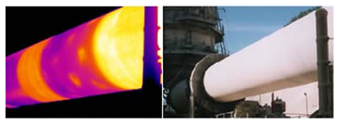
Thermal patterns indicate refractory damage in this lime kiln.
The refractory lining of the kilns eventually wears out and must be replaced. If it is not, the steel shell can overheat and fail. Infrared Thermal Imaging is ideally suited for locating and measuring the temperature of areas where refractory has failed. Continuous tracking allows the kiln operators to maximize the amount of time they can operate until a shutdown for refractory repair is necessary.
Improve the Efficiency of Process Blower Systems
Blower systems can be used to move materials through pipes from one process or location to another. An example might be a system to deliver coal dust to a boiler. The condition of the pipes and process itself can often be monitored with an infrared camera. Buildup of product debris in a pipe will usually show up as a temperature differential in a section of pipe. After the buildup has been removed, Infrared Thermal Imaging can be used to verify that the work has been completed satisfactorily.
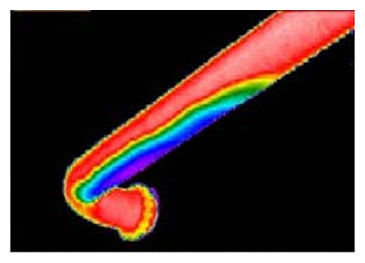
Product buildup can be clearly seen as the cold area on the bottom of the pipe.
Related Articles

Why Record? Infrared Video
What is a Shaft Centerline Diagram?

Gaps in Your Electric Motor Reliability Program
Condition Monitoring of Steam Turbines by Performance Analysis
Implementing an IR Thermography Maintenance Program