Motor Condition Monitor and its Applications in Foundry Industry
from Ibrahim KEYIF*, Ali Riza KAPUCU*, Tugrul DURAKBASA**, Vasfi ELDEM**, Burak GÖKMEN**, Ekrem CESTEPE** * Döktas Dökümcülük Tic. ve San. A.S., TURKEY www.doktas.com.tr ** Artesis Teknoloji Sistemleri A.S., TURKEY www.artesis.com
Abstract
In today’s business environment, manufacturers are faced with the challenge of growing production demands with existing machinery and equipment, while continuing to cut costs. The most pervasive cost that drags down productivity improvements is unplanned equipment and manufacturing process downtime. MCM (Motor Condition Monitor) is a device that continuously monitors electric motors and motor-based machinery and equipment used in several processes in a plant. Thanks to its unique model-based monitoring technology, it has the ability of detecting impending mechanical and electrical failures in these processes at the early stages of fault development. Because of its continuously monitoring feature, several abnormal operations in equipments, processes and plants can come to light, hence the device can be used in process optimisation. The patented model-based monitoring technology that has been used in this device is a consequence of an approximately twenty years’ research activities (U.SA. Patent No : US6014598, Turkey Patent No : TR1998/02541B). The technology has previously found successful applications in space and aviation industries. Keywords : Model-based monitoring, Fault detection and diagnosis, Predictive and proactive maintenance, Electric motor-based machinery and processes
Introduction
The challenge of growing production demands with existing machinery and equipment forces companies to show constant productivity improvements and to get the most from the existing machinery and equipment. The first step to achieve this aim is naturally the online monitoring of the processes in a plant, and the second step that follows is the interpretation of the operational data collected from these processes, so that process optimisation and cost effective productivity opportunities can be identified.
One pervasive cost that drags down productivity improvements, hence process optimisations, is unplanned equipment and manufacturing process downtime. A study on this topic([1]) reveals the fact that machinery and equipment in U.S. plants have an availability between 85%-95% of planned operating time. The cost associated with unplanned downtime might reach 30%-40% of profits.
The high costs resulting from unplanned downtime have attracted attention to maintenance activities in plants. The maintenance of industrial machinery and equipments influences the entire operation of a plant, from equipment availability to product quality. Traditionally, maintenance activities were done either when machinery and equipments failed from time to time, or at regular intervals. But despite of these failure-based and time-based maintenance activities, they were not sufficient to decrease unplanned machinery, equipment and manufacturing process downtime as a result of growing production demands, so this has led to the development of predictive and proactive maintenance concepts. Predictive maintenance program is a condition-based program, which carefully monitors the actual equipment condition, and tries to predict equipment failures before the failure causes downtime. Proactive maintenance, on the other hand, concentrates on pinpointing and eliminating the root causes of equipment failure instead of the symptoms of failure.
MCM (Motor Condition Monitor) is a software and hardware-based product, that has been developed using model-based monitoring technology and is being effectively used for process monitoring, predictive and proactive maintenance activities in different sectors of the industry. It is a device that continuously monitors electric motor-based machinery and equipments (fans, compressors, pumps, press machines, conveyors) used in several processes in a plant and has the ability of detecting impending mechanical and electrical failures (imbalance, misalignment, bearing and rotor faults, leakages, valve and vane misadjustments, isolation and other electrical problems) in these systems at the early stages of fault development using only voltage and current measurements. It can pinpoint several anomalies in an equipment, plant or process that might initiate failure generation. Hence, it prevents unplanned manufacturing downtime and the costs associated with it. Since machinery and equipments are operated at their optimum conditions, the production efficiency of the plant increases. As a result of finding the root causes of failures, the increase in lifetime expectancy of machinery and equipments adds value to the plant. Its easy usage helps the staff that are responsible from the flawless operation of processes to do their work more effectively. The technology used for the detection of impending mechanical and electrical failures is a proven patented technology that has been previously employed in space and aviation applications ([2]-[5]). It was rewarded as one of the 40 best products of year 2000 by Control Engineering Magazine.
Electric Motor-Based Equipment and Process Monitoring
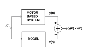
Motor Condition Monitor uses model-based fault detection and diagnosis techniques for monitoring and early failure detection in equipment or processes driven by electric motors. The principle of this approach, as illustrated in Figure 1, is to compare the dynamic behaviour of the mathematical model of the machinery or process with the measured dynamic behaviour. In Figure 1, u(n) is the input to both the mathematical model and the actual motor-based system, in our case, it is the measured voltages. y(n) corresponds to the output of the motor-based system, it corresponds to the measured currents. v(n), on the other hand, is the currents calculated by the model. y(n)-v(n) is the difference between the measured and calculated currents. The model consists of a set of differential equations, which describe the electromechanical behaviour of the motor. The real-time data acquired from the system is processed by system identification algorithms for the calculation of model parameters. The motor driving the machinery or process is being used as a sensor. Faults developing in the motor-based system, or unexpected conditions that affect the operation of the system affect the model parameters. The mathematical model parameters are obtained during a learning period.
Motor Condition Monitor is manufactured as a small, box-shaped device, that is suitable for installation on motor control panels (Figure 2). After the device completes a learning period, it starts to monitor the system by acquiring real-time data from the motor and processing that data to compare the actual condition with the one obtained during the learning mode. If the difference exceeds a set of thresholds, the user is warned by means of a liquid crystal display and a number of light emitting diodes on the front panel of the device. Different light emitting diodes are lighted up depending upon the severity of the impending fault. Fluctuations in line and load conditions are also indicated by lighting up other light emitting diodes.

The device measures only three phase voltage and current signals of a motor, therefore it is highly immune to external influences such as the ones present in vibration measurements. Using the measured three phase voltage and current signals, in addition to the nonphysical model parameters, it calculates a set of physical parameters such as rms-values of three phase voltage and current, powerfactor, etc., therefore monitors the system continuously. This set also includes parameters such as total harmonic distortion, harmonic content of the incoming signal and voltage imbalance which give an idea about the quality of incoming power. Active and reactive power parameters in this set might be used for energy consumption estimations. Therefore, it combines many physical quantities that are of interest to both production and maintenance operators just in one device. A selected physical quantity can be displayed on the liquid crystal display.
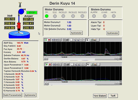
The device can be integrated to SCADA systems using the Modbus communication protocol (Figure 3) and to other maintenance management systems, however it is also possible to use it with its own desktop application, MCMScada. Using this desktop application, the status, physical and nonphysical parameters of several electric motor-based machinery, equipment and processes in a plant can be monitored from several different computers at remote locations. Trend analysis might be performed on the past values stored in a database.
Maintenance activities like improper installation or adjustment might eventually lead to additional failures of machinery and equipment. Frequently, these failures occur very soon after the maintenance activity. Motor Condition Monitor has also the capability of verifying any corrective action taken during a maintenance activity. Comparison of the status of a motor before and after the maintenance activity gives an idea about the quality of corrective action.
Application Examples of MCM in Foundry Industry
Motor Condition Monitor has many successful applications in different areas of industry. In this section, three applications of MCM in foundry industry will be presented.
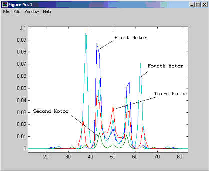
The case illustrated in Figure 4 is an example of the employment of MCM in a well-known Turkish foundry company, Döktas Dökümcülük Tic. ve San. A.S.. In Döktas, Motor Condition Monitor devices were monitoring four identical type motors all of which drive sand mixers. The ‘Model Based Power Spectrum’ of these motors, which are calculated during the learning mode, have been used to assess the status of motors and the processes driven by these motors. The spectra are plotted in Figure 4. It is clear from the figure that the spectra of the first and the second motors have 7.5 Hz side bands around the supply frequency (50 Hz), where as the spectra of the third and the fourth motors have both 7.5 Hz and 12.5 Hz side bands around the supply frequency. The peaks of the side bands are higher in the spectra of the first and the fourth motors when compared to the peaks in the spectra of the second and the third motors. This indicates that the probability of a failure developing in the processes driven by first or the fourth motors is more than the probability of a failure developing in the processes driven by the second and the third motors. This facility enables the user to assess the health of motors, hence to plan maintenance activities.
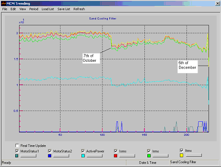
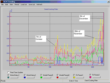
The second example illustrates the application of Motor Condition Monitors in another foundry plant. In this plant, the MCM device was monitoring a sand cooling filter motor. Starting from October 7, 2003, the modelling parameters and errors began to increase gradually as a result of the decrease in currents and power, and the device started to give intermittent ’Load Change’ warnings. As the increase in modelling parameters and models continued, the ‘Load Change’ warnings became more frequent at the end of November. The increase in the level of one of the three phase currents with respect to the other two was an indication of an isolation problem. On December 5, 2003, the motor was repaired. The Motor Condition Monitor device could indicate the deterioration of isolation approximately two months ahead of the actual maintenance activity. Figure 5 illustrates the behaviour of currents, power and motor status signals, and Figure 6 illustrates the corresponding increases in the modelling parameters and models during the development of failure.
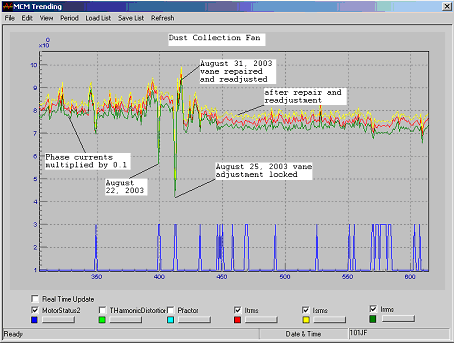
In the last example, the MCM device was monitoring a dust collection fan. The device started to give ‘Load Change’ warning on August 22, 2003. The maintenance team at the plant investigated the problem and observed that one of the vane adjustment gears was locked. The gears were repaired and the vane was readjusted on August 31, 2003. But this time, the position of the vane was slightly different from its previous position, which reduced the flow rate. The technical management of the plant decided to continue the production with the reduced flow rate, but scheduled for further readjustment of the vane position at their earliest convenience. The change in the phase currents of the fan motor is depicted in Figure 7. Using the results provided by the Motor Condition Monitor, a problem in the process was troubleshooted and it was possible to assess the status of the process before and after the maintenance activity. The device is also sensitive to the fullness of dust collection filters.
References
1) D. R. Bell – The Hidden Cost of Downtime : Strategies for Improving Return on Assets, SmartSignal Co., USA, 2003.
2) A. Duyar and W. C. Merrill – Fault Diagnosis For the Space Shuttle Main Engine, AIAA Journal of Guidance, Control and Dynamics, vol. 15, no. 2, pp. 384-389, 1992.
3) A. Duyar, V. Eldem, W. C. Merrill, and T. Guo – Fault Detection and Diagnosis in Propulsion Systems: A Fault Parameter Estimation Approach, AIAA Journal of Guidance, Control and Dynamics, vol. 17, no. 1, pp. 104-108, 1994.
4) J. Litt, M. Kurtkaya, and A. Duyar – Sensor Fault Detection and Diagnosis of the T700 Turboshaft Engine, AIAA Journal of Guidance, Control and Dynamics, vol. 187, no. 3, pp. 640-642, 1995.
5) J. L. Musgrave, T. Guo, E. Wong, and A. Duyar, – Real-Time Accommodation of Actuator Faults on a Reusable Rocket Engine, IEEE Trans. Cont. Syst. Technol., vol. 5, no. 1, pp. 100-109, January 1997.
Related Articles
Principles of Insulation Testing
Top Tips for Selecting Pressure Measurement Transmitters
Gearbox Diagnostics Fault Detection

What is Vibration?

Why Record? Infrared Video
What You Should Know Before you Buy – A Guide to Buying an Infrared Camera


