[webinar] Embracing Digital Transformation in Maintenance & Plant Operations | March 13 at 10AM EST – Register Now
The Benefits of Floating HRSG Duct Liners
The Benefits of Floating HRSG Duct Liners
Brad Buecker – Editor
Buecker & Associates, LLC
Posted 1/30/2024
Introduction
The heat recovery steam generators (HRSGs) of combined cycle power units utilize the exhaust gas from the combustion turbine(s) to generate steam for additional power production. CT exhaust gas temperatures may reach or exceed 1,000o F, and can be even higher if direct fire burners are placed in the HRSG inlet duct. Accordingly, HRSGs have inlet duct liners to keep most of the heat within the duct to maximize HRSG efficiency and to protect plant personnel from what otherwise would be extremely hot duct surfaces. Obviously, duct liners are subject to very harsh conditions, including large temperature swings. The floating liner design allows thermal expansion and helps to give liners greater longevity and performance over rigid liners, as this article explains.
Duct Liner Materials
The three major components of a duct liner are the insulating material, mounting brackets (either studs or scallop plates), and internal liner sheets to protect the insulation from the harsh environment of the hot, rapidly flowing gas stream.
Insulation
The two most common insulating materials are ceramic fiber and fiberglass, with the former being most prominent.
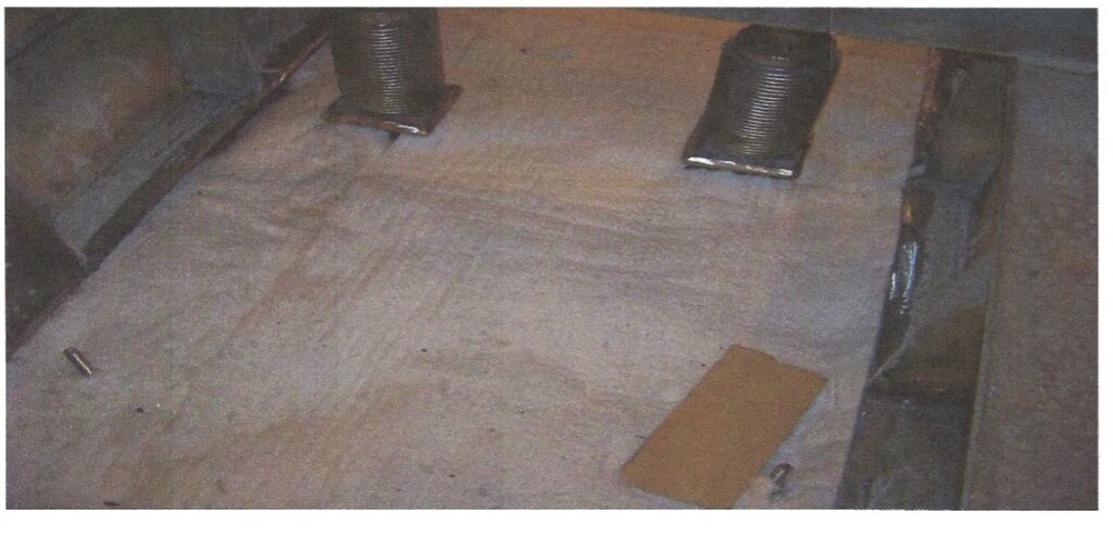
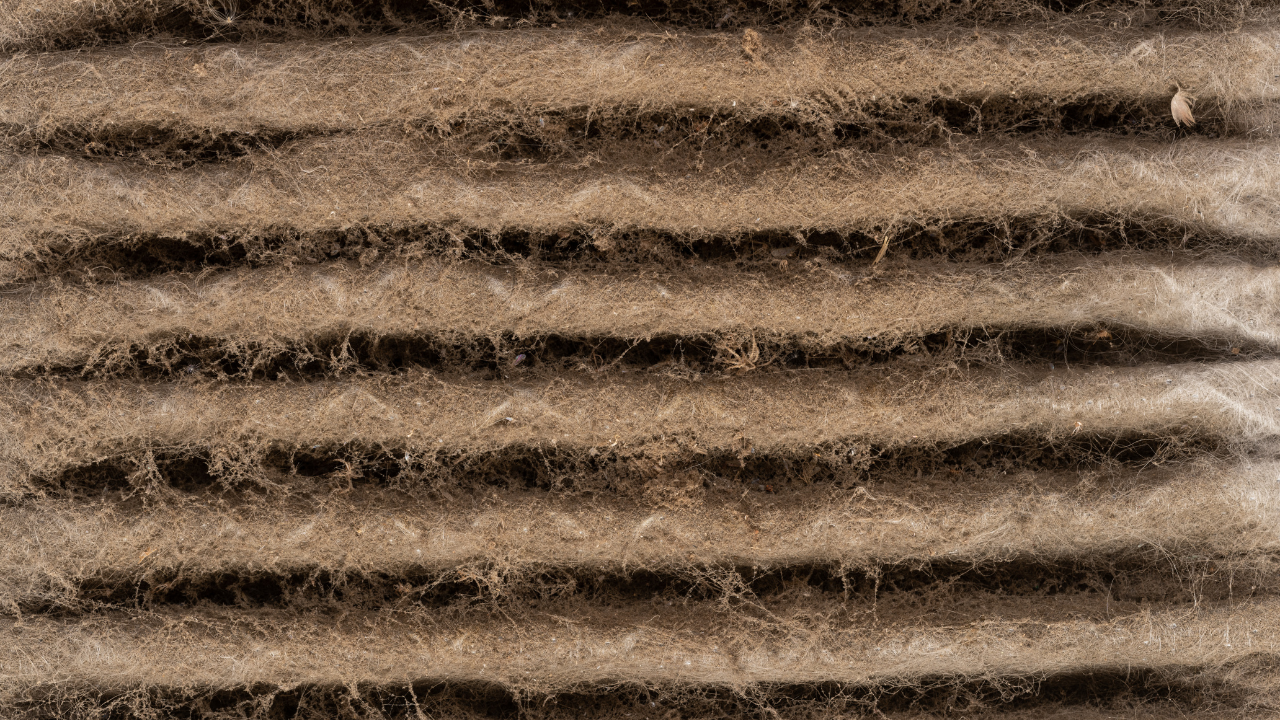
Figure 1. A section of installed insulation without the liner sheet.
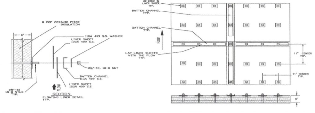
Two primary factors parameters influence insulation selection, thickness and density. Of course, the major objective is to restrict heat loss. However, acoustic mitigation often also comes into play, where the liner design can reduce the noise emitted by the flowing gas through the duct. Figure 2 below shows the basic design details of a 6-inch layer of insulation selected for a 1,200o F gas temperature.
Figure 2. Liner system diagram for a 6” layer of insulation.
Liner Sheets
Without protection, the insulation would rapidly be damaged by the flowing exhaust gas in the inlet duct. Liner sheets offer the needed protection. As shown in Figure 2, a durable material for the sheets is 409 stainless steel, with 11- or 12-gauge thickness being common. Also common are 4’ x 4’ or 4’ x 6’ liner sheets, installed in an overlapping pattern similar to shingles on roofs. Overlap protects the leading edge of every downstream liner sheet from direct impact of the flue gas.
Mounting Brackets
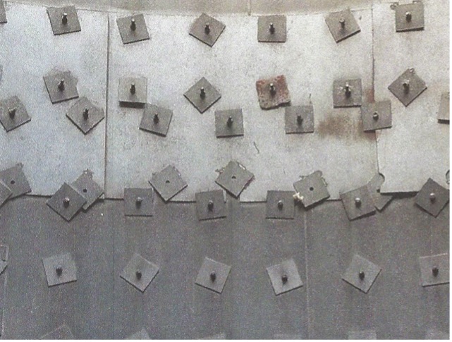
Extremely important is correct design/installation of studs or scallop plates for insulation and liner sheet support. A primary feature of the floating liner concept is to allow expansion and contraction per thermal changes induced by cycling operation. Depending on operating needs, temperatures within the duct can range from 1,300o F to ambient. Figure 2 is based on a computer-designed stud arrangement. Compare that to the haphazard arrangement shown below of a system in need of repair.
Figure 3. A very haphazard stud arrangement for insulation and liner support.
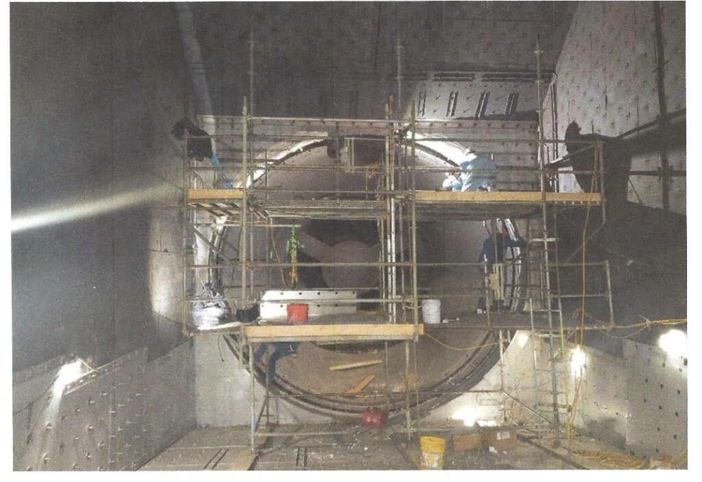
Figure 4 shows the precise stud alignment in a SVI Bremco relining project.
Figure 4. Photo of a relining project underway at the time.
Stud diameters may be adjusted per the support strength needed. Diameters can range from ½” to ¾” or perhaps even 1”, as necessary.
Computational Design Assistance
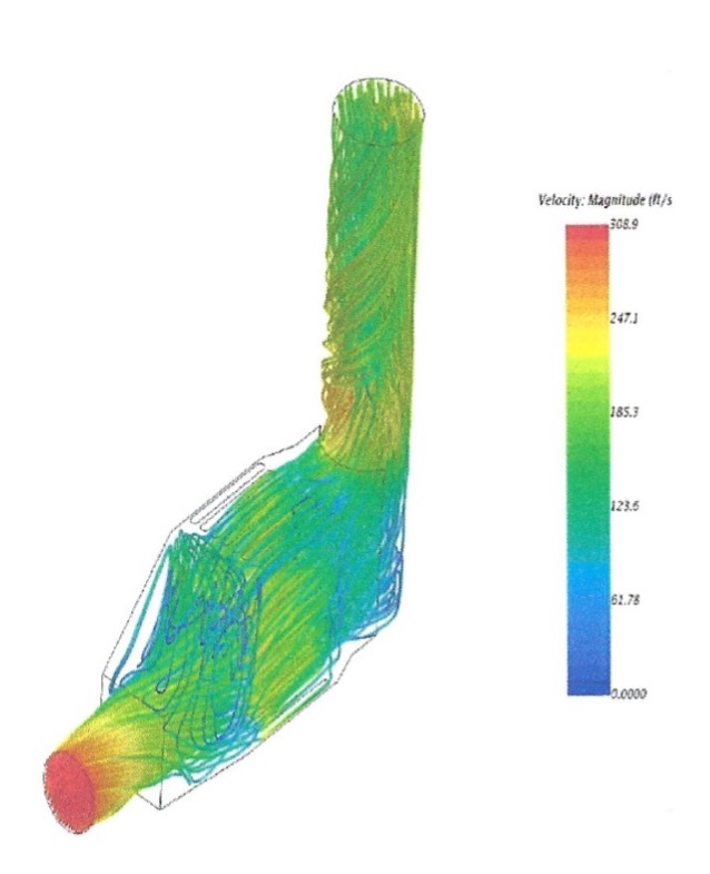
Modern computer and analytical technologies have greatly enhanced design capabilities. Computational fluid dynamics (CFD) software can predict gas flow patterns through the inlet duct, HRSG, and outlet stack.
Figure 5. Example CFD analysis of flue gas flow from the inlet duct through the HRSG and exhaust stack.
CFD data helps to pinpoint locations of maximum flow, which in turn may require adjustments to design parameters that are otherwise acceptable for other locations in the system.
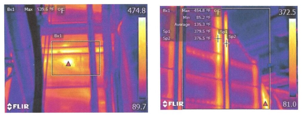
Another valuable technique is thermal imaging of the duct from all sides.
Figure 6. Two thermal images from an existing HRSG inlet duct. The bright areas indicate locations of excessive heat loss. Seams in sectional components are particularly noticeable.
The images can then be utilized to install or repair insulation at “weak” locations. Also, support studs and scallop plates offer a direct path for conductive heat to escape. High temperatures in localized spots can cause metallurgical degradation of the carbon steel outer duct.
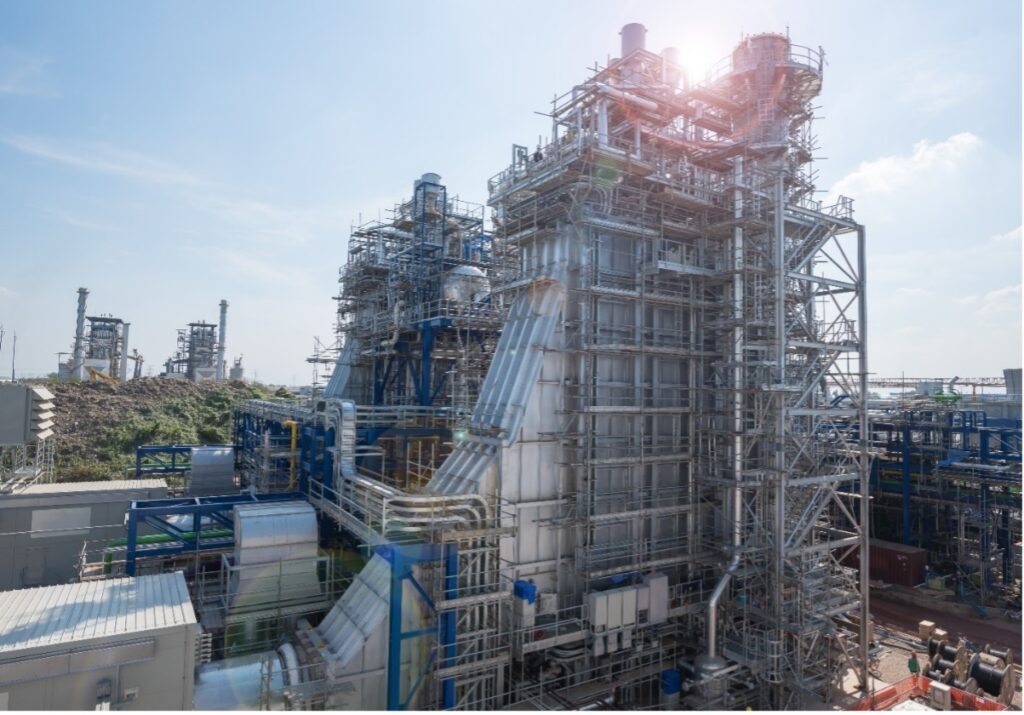
Weak spots and some liner failures may be difficult to observe visually. Consider the typical HRSG design as shown below.
Figure 7. A heat recovery steam generator. Note how the inlet duct greatly enlarges vertically to allow the exhaust gas to contact the HRSG water/steam circuits. (1)
As can be imagined from this photo, accurate visual observation of upper duct and roof areas may be quite difficult. And, it is often not possible or timely to erect scaffolds in these locations for visual inspections or even to make repairs.
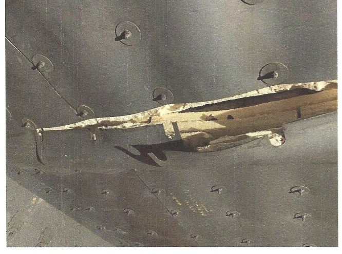
Figure 8. Roof liner failure.
Thermal imaging may be the only viable method to find failed liner locations or other spots of excessive heat loss. Creative methods, including repairs made from the external side of the duct, may be required in difficult-to-access spots.
Conclusion
The harsh environment that exists in HRSG inlet ducts requires careful design/installation of insulation and liner plates. Expansion and contraction issues play a great role in proper design. SVI Bremco personnel can assist with all phases of inspection, repair, and installation of duct insulation, utilizing advanced analytical tools and years of past experience.
Contributing editor for this SVI Bremco article is Brad Buecker.
B. Buecker (Tech. Ed.), “Water Essentials Handbook”; 2023. ChemTreat, Inc., Glen Allen, VA. Currently being released in digital format at www.chemtreat.com.
Brad Buecker
Brad Buecker currently serves as Senior Technical Consultant with SAMCO Technologies. He is also the owner of Buecker & Associates, LLC, which provides independent technical writing/marketing services. Buecker has many years of experience in or supporting the power industry, much of it in steam generation chemistry, water treatment, air quality control, and results engineering positions with City Water, Light & Power (Springfield, Illinois) and Kansas City Power & Light Company's (now Evergy) La Cygne, Kansas, station. Additionally, his background includes eleven years with two engineering firms, Burns & McDonnell and Kiewit, and he spent two years as acting water/wastewater supervisor at a chemical plant. Buecker has a B.S. in chemistry from Iowa State University with additional course work in fluid mechanics, energy and materials balances, and advanced inorganic chemistry. He has authored or co-authored over 300 articles for various technical trade magazines, and he has written three books on power plant chemistry and air pollution control. He is a member of the ACS, AIChE, AIST, ASME, AWT, CTI, and he is active with Power-Gen International, the Electric Utility & Cogeneration Chemistry Workshop, and the International Water Conference. He can be reached at bueckerb@samcotech.com and beakertoo@aol.com.
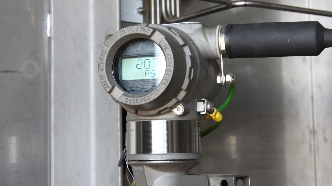
When selecting pressure measurement transmitters, the first stage is whether to opt for a transducer or a transmitter. Although the terms are often confused, there are several differences between transducer and transmitter devices. A transducer creates a low-level electronic signal in response to changes in applied or differential pressure. As with transmitters, transducers feature an internal sensor that converts the applied force into an electrical signal, from which the measurement is derived.
When selecting pressure measurement transmitters, the first stage is whether to opt for a transducer or a transmitter. Although the terms are often confused, there are several differences between transducer and transmitter devices. A transducer creates a low-level electronic signal in response to changes in applied or differential pressure. As with transmitters, transducers feature an internal sensor that converts the applied force into an electrical signal, from which the measurement is derived.
Paul Maier, project manager of the NYSERDA study, states that "Pump sandblasting and coating should be a required step of any pump. refurbishment program." MCWA has also included interior pump coatings as a requirement in its new pump specifications. The goal is that. requiring coatings on the inside of. new pumps will eliminate, or significantly delay, the seemingly inevitable decline in pump performance and efficiency from internal corrosion and tuberculation buildup inside unlined pumps.
Paul Maier, project manager of the NYSERDA study, states that "Pump sandblasting and coating should be a required step of any pump. refurbishment program." MCWA has also included interior pump coatings as a requirement in its new pump specifications. The goal is that. requiring coatings on the inside of. new pumps will eliminate, or significantly delay, the seemingly inevitable decline in pump performance and efficiency from internal corrosion and tuberculation buildup inside unlined pumps.
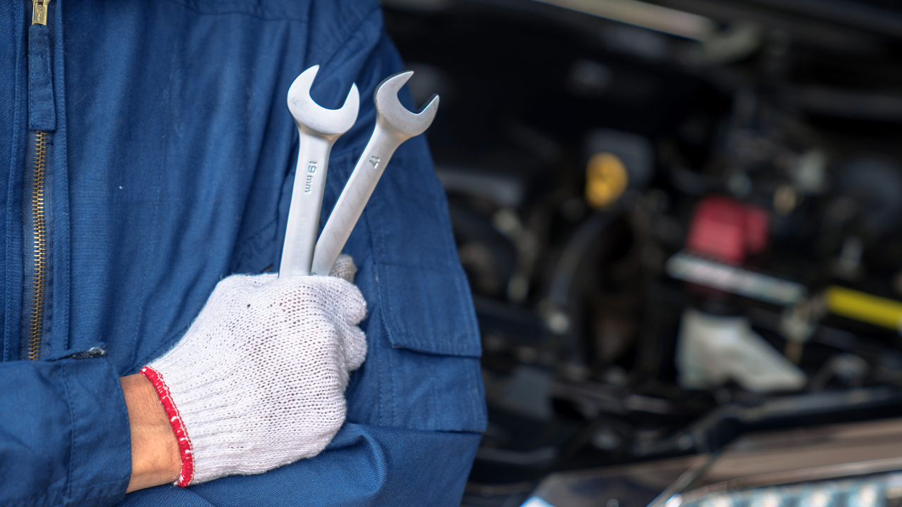
Wrench time is a measure of crafts personnel at work, using tools, in front of jobs. Wrench time does not include obtaining parts, tools or instructions, or the travel associated with those tasks. It does not include traveling to or from Obviously, it does not include break time. These non-wrench time tasks are often necessary to get work done, but are not "wrench time." The craftsperson is in a delay situation. We should also ask ourselves whether the crafts personnel perform tasks efficiently while they are on tools in front of jobs. This is a legitimate question, but not answered by wrench time. Nonetheless, if we increase the time employees are "on the job," we should get more work done.
Wrench time is a measure of crafts personnel at work, using tools, in front of jobs. Wrench time does not include obtaining parts, tools or instructions, or the travel associated with those tasks. It does not include traveling to or from Obviously, it does not include break time. These non-wrench time tasks are often necessary to get work done, but are not "wrench time." The craftsperson is in a delay situation. We should also ask ourselves whether the crafts personnel perform tasks efficiently while they are on tools in front of jobs. This is a legitimate question, but not answered by wrench time. Nonetheless, if we increase the time employees are "on the job," we should get more work done.
Industry spends millions of dollars each year on improved filtration technology in an attempt to reduce particle contamination, with some of the more advanced companies reducing failure rates by up to 90 percent simply by controlling fluid cleanliness. However, in some industries and environments, water is a far more insidious contaminant than solid particles. Water contamination is often overlooked as the primary cause of component failure.
Industry spends millions of dollars each year on improved filtration technology in an attempt to reduce particle contamination, with some of the more advanced companies reducing failure rates by up to 90 percent simply by controlling fluid cleanliness. However, in some industries and environments, water is a far more insidious contaminant than solid particles. Water contamination is often overlooked as the primary cause of component failure.
A long time ago, I discovered that most maintenance people like gadgets and smart methods, especially from within their fields. I must include myself in this group, and have learned to use the knowledge of a variety of maintenance methods to keep up my own enthusiasm while generating interest and commitment for implementing better preventive and corrective maintenance practices. Most of these methods are old, but they are very new to many, especially to people who are just entering the area of maintenance.
A long time ago, I discovered that most maintenance people like gadgets and smart methods, especially from within their fields. I must include myself in this group, and have learned to use the knowledge of a variety of maintenance methods to keep up my own enthusiasm while generating interest and commitment for implementing better preventive and corrective maintenance practices. Most of these methods are old, but they are very new to many, especially to people who are just entering the area of maintenance.
"What's the system's normal operating temperature? What's the system's usual operating pressure range?" If you can't answer these two basic questions about the vital signs of your hydraulic equipment I strongly recommend you make the effort to get to know your hydraulic equipment better. The information is easy to collect and can give valuable insight to the health of your hydraulic equipment.
"What's the system's normal operating temperature? What's the system's usual operating pressure range?" If you can't answer these two basic questions about the vital signs of your hydraulic equipment I strongly recommend you make the effort to get to know your hydraulic equipment better. The information is easy to collect and can give valuable insight to the health of your hydraulic equipment.
Today's new control systems are delivering higher productivity to meet ever-increasing expectations of equipment performance. These systems typically contain more electronics, much of it adopted from non-industrial applications, and almost all of it more sensitive to electrical disturbances than the equipment being replaced. The following discussion provides information needed to develop a strategy for protecting sensitive mission critical equipment from the effects of a poor industrial power environment.
Today's new control systems are delivering higher productivity to meet ever-increasing expectations of equipment performance. These systems typically contain more electronics, much of it adopted from non-industrial applications, and almost all of it more sensitive to electrical disturbances than the equipment being replaced. The following discussion provides information needed to develop a strategy for protecting sensitive mission critical equipment from the effects of a poor industrial power environment.
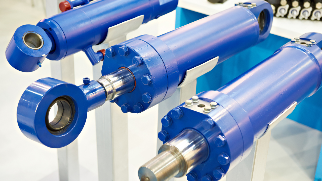
Damaged hydraulic cylinder rods and wiper seals are an eternal problem for users of hydraulic machinery. Dents and gouges on the surface of hydraulic cylinder rods reduce seal life and give dust and other contaminants an easy path into the hydraulic system. Many hydraulic cylinders also have bent rods, which cause distortion and ultimately premature failure of the seals.
Damaged hydraulic cylinder rods and wiper seals are an eternal problem for users of hydraulic machinery. Dents and gouges on the surface of hydraulic cylinder rods reduce seal life and give dust and other contaminants an easy path into the hydraulic system. Many hydraulic cylinders also have bent rods, which cause distortion and ultimately premature failure of the seals.
This project, like so many others, had a humble beginning. About five years ago, after returning from a routine sales call to the smelter where a representative was selling synthetic and specialty greases, he challenged the authors to develop a series of lubricants that he could sell to the aluminum industry. In a discussion with a group of maintenance people at the smelter, he was told that if his company could develop longer lasting lubricants and protect equipment better than the current product, they would buy from him.
This project, like so many others, had a humble beginning. About five years ago, after returning from a routine sales call to the smelter where a representative was selling synthetic and specialty greases, he challenged the authors to develop a series of lubricants that he could sell to the aluminum industry. In a discussion with a group of maintenance people at the smelter, he was told that if his company could develop longer lasting lubricants and protect equipment better than the current product, they would buy from him.
When we think of contamination in lubricated systems, we often focus on particle and water contamination. The fact of the matter is that there are many other contaminants we should consider and attempt to control. Most contaminants, which include any material not contained in the lubricant's formulation, can potentially damage the oil and the lubricated components. Although air is always present in lubricating oil, it is often justifiable to adopt measures to minimize its presence.
When we think of contamination in lubricated systems, we often focus on particle and water contamination. The fact of the matter is that there are many other contaminants we should consider and attempt to control. Most contaminants, which include any material not contained in the lubricant's formulation, can potentially damage the oil and the lubricated components. Although air is always present in lubricating oil, it is often justifiable to adopt measures to minimize its presence.
In today's industry, practices that were once acceptable are no longer even tolerated. Environmental concerns and EPA mandates are applying more and more pressure on businesses like the chemical industry to improve the manufacturing processes being used, to the point that not only is a slight drip from a pump seal not acceptable, but in 2004 the MACT will be enacted and only 500 - 1,000 parts per million vapor will be allowed and, eventually, no vapor at all.
In today's industry, practices that were once acceptable are no longer even tolerated. Environmental concerns and EPA mandates are applying more and more pressure on businesses like the chemical industry to improve the manufacturing processes being used, to the point that not only is a slight drip from a pump seal not acceptable, but in 2004 the MACT will be enacted and only 500 - 1,000 parts per million vapor will be allowed and, eventually, no vapor at all.