Identifying Motor Defects Through Fault Zone Analysis
ELECTRICAL maintenance personnel have for years been limited to troubleshooting with no more than a fluke and a Megger. This unfortunately does not provide enough information to allow most electricians to feel totally confident in determining if an electrical problem exists or not. A mechanical operator once said, “If a problem exists with a piece of equipment, and there is an electric cable within ten feet of it, then it must be an electrical problem!” If you are involved with electric maintenance you have probably heard at some time in your career, “It must be the motor.” If you are into mechanical maintenance you have likely heard, “It’s probably the pump. Lets uncouple it.”
This has been an on-going battle and, up to recently, technology has been primarily developed for the mechanical side. Vibration shows a two times line frequency (2FL) spike and that must mean it’s electrical. Right?… Wrong!!!! There are so many variables producing a 2FL today that removing a motor from service for an electrical repair due only to a high 2FL is a mistake. Possibly an expensive one. The best thing you could hope for is that the repair facility will call back asking “what do you want done?” to this perfectly good motor.
“RESISTANCE to ground or megger testing is all we need.” I find this statement hard to believe. How many times as an electrician have we been nervous restarting a tripped motor after verifying with our trusty megger that, “The motor is fine.” The fact is, numerous reasons can exist which causes a motor to trip that will not be seen by a megger, such as a turn to turn short. Breakdown in the insulation between individual turns of a winding can occur inside a stator slot or at the end turn and be completely isolated from ground. Phase to phase shorts can occur the same way. If these faults are left unattended, they can result in rapid deterioration of the winding, potentially ending in a complete motor replacement. Restarting of a motor that has tripped should be considered only after these faults have been factored out.
TROUBLESHOOTING an electric motor that is suspected to have an electrical problem should not result in the statement, “ The motor is fine.” Although someone with years of experience and tons of credibility may be able to get away with such a simple statement, most electricians won’t find the same positive response from their supervisor, engineer, or plant manager. To confidently report the electrical condition of a motor and ensure that your recommendation is taken seriously, there are six areas of interest known as Fault Zones that must be looked at during the troubleshooting effort. Missing any of these zones could result in missing the problem and losing credibility in our skills.
The six electric Fault Zones are:
1. Power Quality
2. Power Circuit
3. Insulation
4. Stator
5. Rotor
6. Air Gap
Power Quality: has recently been thrust in the limelight by utility deregulation and the popularity of AC and DC drives. With deregulation, competition among utilities has heightened the concern of penalties from high distortion levels. The variable frequency drives (VFD’s) and other non-linear loads can significantly increasing the distortion levels of voltage and current. How can this distortion be minimized? What equipment is required, and is the concern purely financial or is equipment at risk?
First, let’s understand what we are really talking about when we speak of power quality problems. Voltage and current harmonic distortion, voltage spikes, voltage unbalance and power factor are a few of the many concerns when discussing power quality. Although all of these are important, we will focus on just a few, beginning with harmonic distortion.
Harmonic Distortion always sounds like such an in-depth concept. It becomes more elementary if you break it down to the basic fundamentals. The most common reference in this topic is Total Harmonic Distortion (THD). THD is the ratio of the root-mean-square of the harmonic content to the root-mean-square value of the fundamental quantity, expressed as a percent of the fundamental. Quite simply it is the RMS value of the signal with the line frequency(fundamental) removed. A perfect 60 Hz sine wave would have 0% THD. So anything other then the fundamental line frequency (60 Hz) would be considered a harmonic distortion.
Common non-linear (switching) loads include computers, florescent lighting and variable frequency drives (VFD’s) as mentioned previously. The presence of harmonics in a distribution system results in excessive heat from the increased current demands. A load designed to pull 100 amps at full load may draw now 120 amps if the harmonic distortion is high. This additional current can lead to insulation damage and possibly a catastrophic failure. Excessive zero sequence harmonics will collect back at the transformer, leading to overload and possible failure. These high zero sequence currents return to the source through the neutral bus, and, if excessive, can generate substantial heat and even fires. In an effort to avoid such catastrophic events, many companies are modifying their distribution systems. Installing k-transformers, designed to handle the larger loads generated by harmonics, and increasing the mil size of their neutral to accommodate larger current levels are two popular activities. Though these efforts do nothing to diminish the harmonics, they do reduce the failure risk. Removing the harmonics requires the installation of filtering mechanisms, such as zero sequence filters.
Some of the newer VFDs that utilize IGBTs can exceed line voltage by a tremendous amount in less than a microsecond. Older class B insulation systems have low tolerance for this rapid rise time and can fail very quickly. Motors designed for inverter duty are highly recommended when utilizing drives. Excessive cable length between the drive and the motor can create a high impedance mismatch that contributes to high voltage spikes at the motor connection box. The drive manufacturer will normally specify the correct cable distance.
General guidelines as stated in Table 3.3.1 of IEEE 519-1992, recommend <5% voltage THD for systems operating <69kv. They further recommend the individual harmonic voltage distortion to be <3%. Figure 1 shows an example of unacceptable levels of voltage distortion. These high harmonic levels can be seen on the voltage signal as pulses riding the fundamental frequency (figure 2).
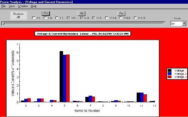
Figure 1
High 5th and 7th harmonics indicate the presence of a 6 pulse drive influence on the distribution system. Each of the individual harmonics should be <3% of the fundamental per IEEE 519-1992.
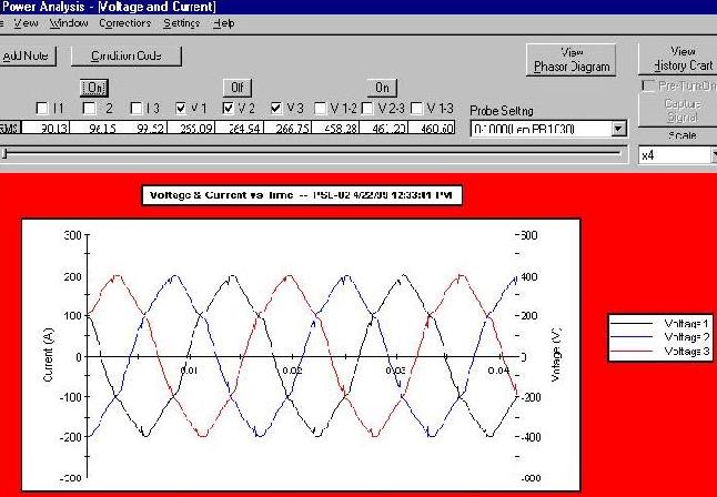
Figure 2
Figure 2 shows a fundamental 60 Hz voltage signal with 6 pulses occurring throughout each sinewave. This resulted from an unfiltered 6 pulse drive connected to the distribution system.
Power Circuit: What is a Power Circuit? The power circuit refers to all the conductors and connections that exist from the point at which the testing starts through to the connections at the motor. This can include circuit breakers, fuses, contactors, overloads, disconnects, and lug connections. A 1994 demonstration project on industrial power distribution systems found that connectors and conductors were the source of 46% of the faults reducing motor efficiency. Many times a motor, although initially in perfect health, is installed into a faulty power circuit. This causes problems like harmonics, voltage imbalances, current imbalances, etc. As these problems become more severe, the horsepower rating of your motor drops, causing temperatures to increase and insulation damage to occur. This motor is replaced many times and the failure cycle begins again. As seen in figure 3, high resistance connections resulting in voltage imbalances will reduce the horsepower rating significantly.
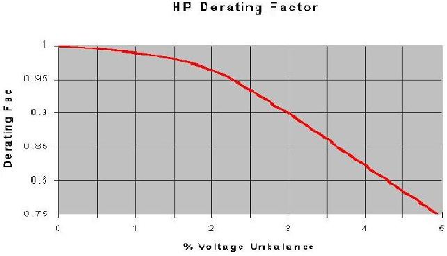
Reference: NEMA Standards MG 1-14.35
Figure 3
One method of detecting high resistance connections is by performing phase to phase resistance testing. On a three phase motor, the three resistance measurements should be nearly identical. If all three reading are exactly the same, there would be a 0% resistive imbalance. As one or more phases develop a high resistance the resistive imbalance increases, indicating a fault.
Some of the fault mechanisms that cause high resistance connections are:
- Corroded terminals
- Loose cables
- Loose bus bars
- Corroded fuse clips
- Corroded contacts
- Open leads
- Different size conductors
- Dissimilar metals
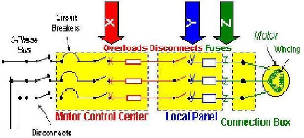
Figure 4
Figure 4 shows three different resistance test points which can be used to determine the actual location of the high resistance connection. Position X is upstream of the fuses. If the resistive imbalance is still high, you may want to move to position Y, down stream of the contactor. If the imbalance is still evident at position Y, testing at the motor connection box, position Z, will isolate the motor from the power circuit and determine which is the problem area.
Insulation Condition: This refers to the insulation between the windings and ground. High temperatures, age, moisture, and dirt contamination all lead to shortened insulation life. It has been said that if plants would just use the space heaters available to keep the insulation dry, then doubling the life of our motors would not be out of the question.
Insulation systems today are better than ever and are able to handle higher and higher temperatures without significant reduction in life. However, we are still finding ways to destroy our insulation much earlier than should be expected. Keep in mind that although insulation is many times involved in a failure, this fault zone is heavily influenced by other problems. The power circuit for one can heavily influence the insulation. If a high resistance connection exists upstream of the motor, which develops better than a 5% voltage imbalance, and we continue to run the motor at its normal Hp rating, we will see a shortened insulation life. Reverse sequence currents developing rotating magnetic fields in the opposite direction will not only reduce the torque capability, but can allow the temperature to rise out of control and exceed even the 150 0C limit on your class F insulation systems. Was the insulation system the real cause of the motor failure or was it just a symptom? It is easy to diagnose the evident insulation failure as the fault mechanism but it will happen again with a different motor if the problem is not fixed. Then what will the explanation be?
Again, testing with a megger is not going to tell you everything, but it is a good start when it comes to insulation testing. Something that people often overlook when it comes to the IEEE (Institute of Electrical and Electronic Engineers) limits on resistance to ground is the reference to 40 0C. Simply megger testing with no regard to temperature will result in resistance to ground readings, which swing heavily from high to low readings, depending on the temperature of the windings. Temperature correcting the readings will not only meet the IEEE testing requirements, it will give a much better trend as seen in Figure 5.
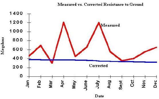
Figure 5
We must realize that moisture contamination may cause the temperature corrected reading to be invalid. Ensure the heaters are energized when the motor is not running to prevent this from happening.
An insulation test that has fallen out of the spotlight is the Polarization Index test. Applying a constant DC voltage, in the form of a megger test, for a period of 10 minutes will result in a gradual increase in the resistance to ground (RTG) reading. This is a result of charging the insulation system, much like a capacitor, which causes a reduction in the absorption current. Per ohms law, I(current) = V(voltage) / R(resistance). Therefore, the reduction of this absorption current must result in an increase in the resistance. If we take the ten minute RTG and divide it by the one minute RTG, a value of 2.0 or higher is considered acceptable by IEEE. Unfortunately, motors with unstable insulation systems can give values close to or greater then a 2.0, but still be defective.
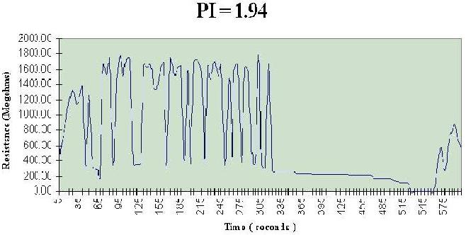
Figure 6
In Figure 6, when the ten minute reading (approximately 600 megohms) is divided by the one minute reading (approximately 300 megohms), the result is 1.94. This nearly meets the IEEE specification as a good insulation system, and would probably be accepted in the field. You can see, however, that this insulation system is very unstable. Always look at the PI Profile and not just the Index.
A limiting factor about DC resistance to ground testing is that the DC signal will many times not give the best evaluation of the true insulation condition. The insulation on a motor is a natural dielectric material. Therefore it is a poor conductor of DC. This is good because you don’t want excessive leakage to ground, but bad in that an insulation system in a degraded condition may take a bit longer to be identified using a DC signal or megger. AC however, does not allow the dielectric to charge and will pass through the dielectric much easier. This is good because it allows the use of an AC signal to give much earlier indications of insulation degradation and bad because it can be destructive, as with an AC Hi-Pot. Low voltage capacitance to ground tests, however, are non destructive and very good early indicators of degradation modes in your insulation systems. These values will be read in pico farads (pF) and can be effectively trended over time.
Stator Condition: What is a Stator? When we mention the stator, we are referencing the DC or 3 phase AC windings, insulation between the turns of the winding, solder joints between the coils, and the stator core or laminations.
One of the common faults occurring with motor windings is a turn to turn fault. This occurs when the insulation between two turns in the same coil breaks down and reduces the coil’s ability to produce a balanced magnetic field. Unbalanced magnetic fields result in vibration, which can then cause degradation of the insulation as well as bearing failures. Localized heating around the short can also spread to other coils, resulting in a coil to coil short. Excessive heating will eventually not only destroy the motor windings, but will also damage the insulation between the laminations of the stator core.
Another fault that can occur with motor windings is a phase to phase fault. This results from the insulation breaking down between two separate phases, usually lying adjacent to each other in the same slot. A higher difference in voltage potential tends to make this fault accelerate very quickly. Slot paper is installed between different phases in the same slot to reduce the opportunity for leakage between phases.
A turn to turn or a phase to phase short can occur many times without resulting in an immediate ground fault. Because of this, testing with just a megger for preventive maintenance or following a motor trip may not identify the fault. This could cause a small winding fault to develop into a major catastrophic failure. Permanent core damage may necessitate replacing an entire motor.
Testing of the stator can be done by connecting directly at the motor as well as connecting at the MCC. During the test, high frequency AC signals are sent into the motor. These signals produce magnetic fields around the windings which should be matched between phases. The inductance measurement for each phase is then compared to the other phases and calculated into an inductive imbalance. This imbalance minus the influence of the rotor is used to compare the ability of each of the phases to produce a balanced magnetic field.
Also during a test, DC signals are sent into the motor. From these signals the actual resistance of the winding or windings is measured. The three resistance readings of a three phase induction motor are compared and calculated to produce a resistive imbalance. If this imbalance exceeds a predetermined level, then high resistance connections may exist in the solder joints between coils.
There are two basic types of stator winding configurations. The first is wye (or “Y”) connected and the second is delta connected. To more fully understand what the inductance readings are telling you, a simple understanding of the winding configuration can help.
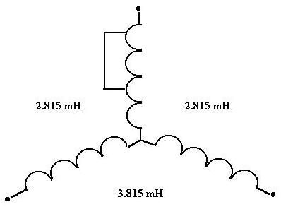
Figure 7
A “Y” configuration winding with a turn to turn short will result in two low inductance readings and one high inductance reading, when looking at phase to phase inductance.
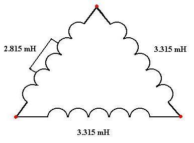
Figure 8
A delta configuration winding with a turn to turn short will result in one low inductance reading and two high inductance readings, when looking at phase to phase inductance.
Rotor Condition: This refers to the rotor bars, the rotor laminations, and the end rings of the rotor. In the 1980s, a joint effort between EPRI and General Electric showed that 10% of motor failures were due to the rotor. The rotor, although a small percentage of the motor problems, can influence other fault zones to fail. When a motor is started with a broken or cracked rotor bar, intense heat is generated around the vicinity of the break. This can spread to other rotor bars and destroy the insulation around the nearby laminations. It can also effect other parts of the motor. What is just a few millimeters away from the rotor? The stator! Stator insulation can not hold up to the intense heat developed by the broken rotor bar and will eventually fail. Unfortunately, many times broken rotor bars are not easily seen without technology and it may be missed as the root cause of failure. This will result in a motor rewind, and replacement of bearings, but not a rotor repair. When the motor returns to service, it has the same problem all over again, just with new insulation to destroy.
One method of testing the rotor condition is the Rotor Influence Check (RICTM). What is a RIC? The RIC is a test performed on AC induction, synchronous, and wound rotor motors which illustrates the magnetic coupling between the rotor and stator. This relationship indicates the condition of the rotor and air gap within the motor.
The Rotor Influence Check is performed by rotating the rotor in specific increments (determined by the number of poles) over a single pole group, and recording the change in inductance measurements for each phase of the 3 phase motor. For proper resolution, 18 inductance measurements per pole group are recommended. To determine the number of poles in a motor use the following equation.
F = NP / 120
F = Line Frequency (normally 60hz in US)
N = Speed of the motor in RPM
P = # of poles
Recalculated: P = 7200 / RPM
Example: A motor with name plate RPM = 1780 would have how many poles?
P = 7200 / 1780
= 4 poles
Without historical data, a RIC must be performed to provide any information about the standard squirrel cage induction rotor. Faults such as broken rotor bars or damaged laminations can exist even if the balance of inductance is low. If you are basing the decision to perform a RIC only on how high the balance of inductance is on the baseline test, you could be overlooking late stages of rotor bar defect.
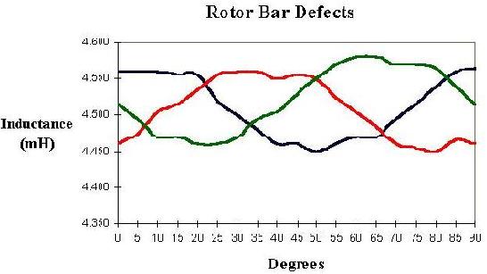
Figure 9
Figure 9 shows the expected inductance changes for a rotor with broken rotor bars. Note the erratic inductance values at the peak of the sinewaves for each phase. Broken rotor bars cause a skewing in the field flux generated by and around the rotor bars. A normal rotor would have no skewing or erratic inductance patterns, as seen in Figure 10.
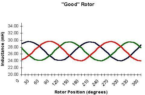
Figure 10
Rotor / Stator Relationship: This relationship references the air gap between the rotor and stator. If this air gap is not evenly distributed around the 360 degrees of the motor, uneven magnetic fields can be produced. These magnetic imbalances can cause movement of the stator windings, resulting in winding failure, and electrically induced vibration, resulting in bearing failure. A faulty relationship between the rotor and stator is also called an eccentricity.
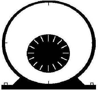
Figure 11
The first type is called static eccentricity. Figure 11 and Figure 12 show an example of what static eccentricity looks like, physically and inductively. This type of eccentricity is caused by problems like a misaligned endbell or the shaft sitting low in the bearing. The physical result is that the shaft is always in the same place out of the electric center.
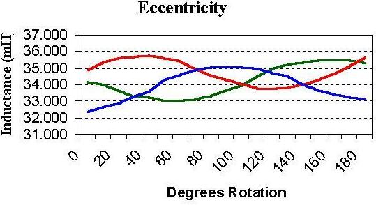
Figure 12
The inductive result is the variation in peaks of the sinewave as seen in Figure 12.
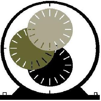
Figure 13
The second type of eccentricity is called dynamic eccentricity. This results when the rotor does not stay in one place but is allowed to move within the space of the stator as seen in Figure 13.
The inductive result is the movement of all three inductance values up or down, depending on which phase is closest to the rotor at a given degree rotation. This is seen in Figure 14.
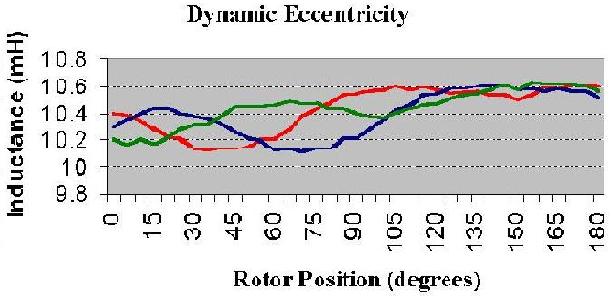
Figure 14
In conclusion, the term “The motor is fine” is just not enough to ensure that we are taken seriously and that a true assessment of the motor health has been performed. If the decision is up to you as to what to do in a troubleshooting or diagnostic situation, look at the whole picture. If at all possible, do not make a quick decision. Break the system down into its individual fault zones, test each fault zone completely with every technology available to you, and finally make your recommendations written or verbal using the terminology used in fault zone analysis to express your confidence and capabilities.
Related Articles


How to Optimize Operations and Maintenance for Success

Manufacturing Operations Management: How Processors can take a New Approach to Raw Material Price Inflation

Skills Shortage: The Perfect Storm Intensifies

Maintenance Cost and Estimated Replacement Value

How Can Control Systems Trick Operators?