

An Engineer’s Guide to Robots: Most maintenance engineers have the same instinct
Ahmed Rezika, SimpleWays OU
Posted 8/5/2026
When a new machine arrives, they rarely stop at reading the brochure. They want to know what is inside. They want to understand how every subsystem contributes to the whole machine. They mentally dismantle it, trace signals, inspect components, and imagine failure modes long before the first maintenance schedule is written.
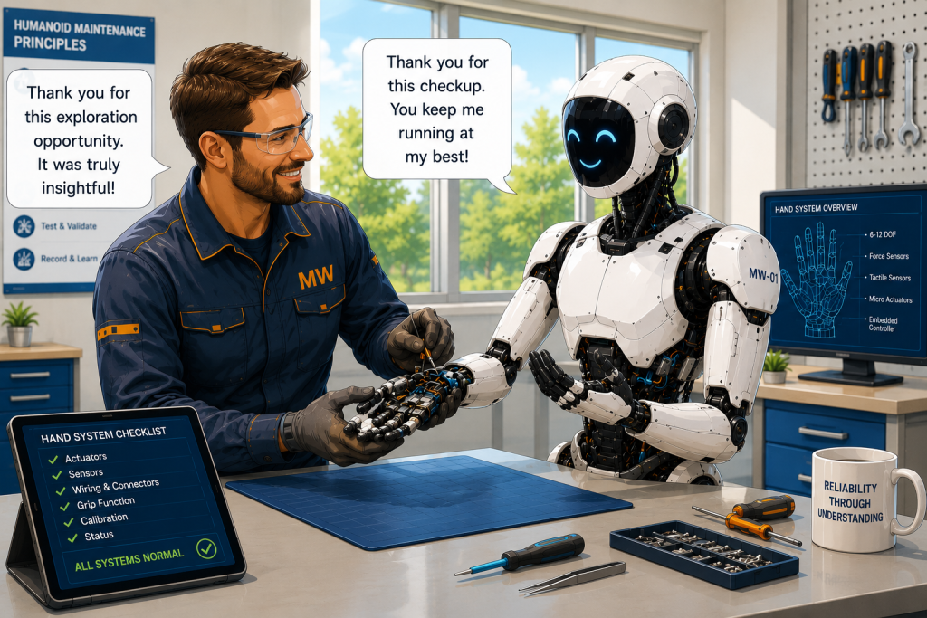
Imagine, then, that your newest maintenance colleague is not another technician but a humanoid robot. During a planned shutdown, your team decides—not to repair it—but to explore how it is built. The humanoid willingly participates, explaining each subsystem as its outer panels are removed.
This article follows that imaginary conversation. While fictional, every subsystem described reflects technologies that already exist in today’s advanced humanoid robots. By the end, you will not simply know what a humanoid can do—you will understand how it is physically constructed, why each component exists, and which maintenance disciplines come together to keep it operating.
Removing the Outer Shell: The First Engineering Explorations
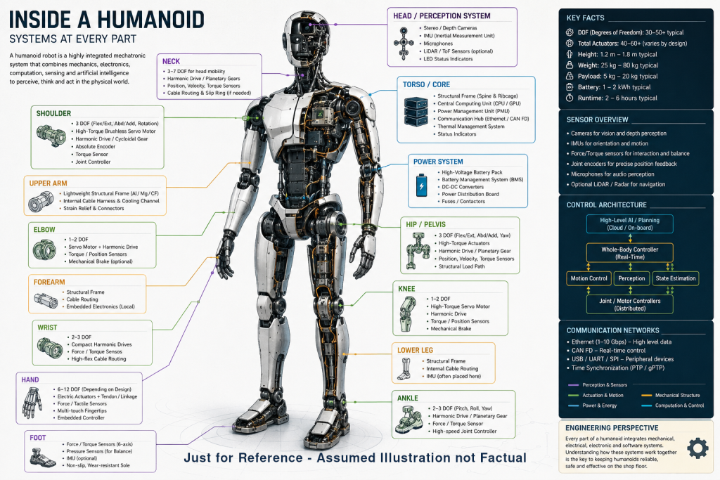
As the maintenance team begins removing the external body panels, the first surprise is how familiar the internal architecture appears. Although humanoid robots often attract attention because of their human-like appearance, their internal construction is fundamentally an integration of well-established engineering disciplines rather than entirely new technology. Beneath the cosmetic shell are structural members, electrical harnesses, communication networks, distributed control electronics, sensors, actuators, thermal management components, and power distribution systems—many of which would be recognizable to engineers working with modern industrial automation.
External Body
The external covers themselves are designed with multiple objectives in mind. Besides providing an anthropomorphic appearance, they protect internal components from dust and accidental contact, improve aerodynamic flow for cooling in some designs, reduce noise transmission, and provide safe interaction surfaces for humans. Depending on the manufacturer, these panels are commonly fabricated from engineering plastics, carbon-fiber composites, glass-fiber reinforced polymers, or lightweight aluminum assemblies. Material selection is always a compromise between impact resistance, stiffness, weight, manufacturability, repairability, and cost. Similar design trade-offs are already familiar in industries such as aerospace, automotive, and collaborative robotics.
Internal Discoveries
As additional panels are removed, the engineers notice that there is no equivalent of the large electrical cabinet typically found beside an industrial production line. Instead, the electronics are distributed throughout the body. Local motor controllers are positioned close to individual joints to reduce cable lengths, improve electromagnetic compatibility, and minimize transmission losses. Higher-level computing units are usually located within the torso, where they can benefit from improved cooling, centralized power distribution, and easier maintenance access. This distributed architecture reflects a growing trend in industrial automation, where intelligence is increasingly moved closer to field devices through edge computing and decentralized control.
Cable routing immediately attracts the attention of experienced maintenance engineers. Hundreds of power, communication, and sensor conductors must pass through rotating joints while remaining protected against fatigue, torsional stress, and repeated flexing. Designers therefore employ flexible cable carriers, carefully defined bend radii, strain-relief mechanisms, and modular connectors to maximize service life. Similar challenges have long existed in industrial robot arms, cable reels, offshore equipment, and machine tools, but a humanoid robot multiplies these challenges because almost every major joint is continuously moving while simultaneously carrying power, high-speed data, and sensor signals.
Another observation becomes clear during the inspection: unlike traditional industrial machines, where mechanical, electrical, and control systems are often physically separated, humanoids integrate these disciplines into compact modular assemblies [1]. A shoulder, elbow, or knee is not simply a mechanical joint. It is a complete mechatronic module containing structural components, bearings, high-performance actuators, precision gear reductions, multiple sensors, embedded electronics, communication interfaces, and thermal management features. This high degree of functional integration reduces overall size and weight but also changes maintenance practices. Troubleshooting increasingly requires understanding the interactions between mechanical wear, electrical performance, embedded software, communication timing, and sensor calibration rather than examining each discipline independently.
By the time the first inspection is complete, the team realizes that the humanoid is neither an oversized collaborative robot nor a miniature production line. It is better understood as a highly integrated mechatronic platform that compresses decades of advances in mechanical engineering, power electronics, embedded systems, artificial intelligence, materials science, and industrial communications into a human-sized machine. Recognizing this architecture is the first step toward understanding how humanoids can eventually become maintainable assets within industrial facilities rather than technological curiosities.

Beneath the Skin: The Structural Skeleton and Why It is difficult to match Human
Unlike conventional industrial robot arms that are typically bolted to rigid foundations, humanoids are continuously balancing while simultaneously performing useful work. This introduces structural requirements that are rarely encountered in traditional factory automation. Every movement of an arm alters the robot’s center of mass, requiring the torso, hips, legs, and ankles to compensate almost instantaneously. Consequently, the structural frame is designed not only to support static loads but also to withstand continuously changing dynamic forces generated during walking, climbing, lifting, and recovering from external disturbances. Structural stiffness becomes critical because even small deflections can affect joint alignment, sensor accuracy, and closed-loop motion control.
Recent humanoid designs increasingly employ lightweight aluminum alloys as the primary structural material, combined with high-strength steel inserts at heavily loaded interfaces such as hip joints, knee pivots, and actuator mounting points. Some manufacturers also incorporate magnesium alloys or carbon-fiber composite components to reduce mass in limbs where lower inertia directly improves agility and reduces actuator power requirements. Every kilogram removed from a moving limb decreases rotational inertia, allowing faster acceleration, shorter stopping distances, and lower energy consumption. This relationship explains why structural optimization is often as important as advances in motors or artificial intelligence.
Bones, Nerves, Muscles & More
Unlike the human body, where muscles naturally provide compliance and absorb disturbances, humanoids must actively create stability through their actuators. Modern humanoids continuously estimate their center of mass (CoM), center of pressure (CoP), and the position of the Zero Moment Point (ZMP)—the point on the supporting foot where the resultant ground reaction force acts. As long as the ZMP remains within the support polygon formed by one or both feet, the robot can theoretically maintain balance. The concept, first formalized by Miomir Vukobratović in the late 1960s, remains a cornerstone of humanoid locomotion, although many recent systems extend it using whole-body dynamic control and model predictive control (MPC).
To estimate these quantities, the robot combines information from multiple sensing systems[2]. An Inertial Measurement Unit (IMU), typically located close to the torso, continuously measures angular velocity and linear acceleration. Six-axis force/torque sensors, often integrated into the ankles or feet, measure the interaction between the robot and the floor. High-resolution joint encoders report the exact position and velocity of every actuator, while stereo cameras, depth sensors, and increasingly LiDAR systems contribute information about terrain geometry and approaching obstacles. None of these sensors is sufficiently reliable on its own. Instead, sensor fusion algorithms—often based on variants of the Kalman Filter or factor graph optimization—combine these independent measurements into a consistent estimate of the robot’s state hundreds or even thousands of times per second.
Recent humanoids have moved beyond simply maintaining balance; they actively anticipate losing it. Whole-body controllers calculate how movement in one limb should be compensated by coordinated motion in the rest of the body before instability occurs. If the robot reaches forward to lift a toolbox, the torso may lean backwards while the ankles generate counteracting torque and the opposite arm shifts position to maintain the overall center of mass. This resembles the unconscious adjustments humans make every day but requires solving complex optimization problems in real time. Modern approaches frequently employ Model Predictive Control (MPC), where the controller continuously predicts future body motion over a short time horizon and selects actuator commands that minimize instability while respecting joint limits, motor torque constraints, and contact forces.
Sensitivity of the Design
Mechanical design plays an equally important role. Engineers often focus on algorithms, yet balance begins with mass distribution. Heavy components—including battery packs, high-performance computers, and power electronics—are generally concentrated within the torso, close to the robot’s natural center of mass. The limbs are intentionally designed to be as light as possible, reducing rotational inertia and enabling faster corrective movements. This design philosophy mirrors high-speed industrial automation, where lightweight end effectors and moving axes reduce energy consumption while improving dynamic performance.
For maintenance engineers, this highlights an important difference from conventional machinery. A seemingly minor intervention—replacing a battery with a heavier model, modifying cable routing, installing a larger sensor, or adding protective guarding—may alter the robot’s mass distribution enough to require recalibration of its balance controller. In traditional machinery, additional weight is often little more than a structural consideration. In humanoids, every gram contributes to the dynamic model that the control system relies upon. Mechanical modifications therefore become software considerations as well, reinforcing the close coupling between physical construction and intelligent control.
The Thought Experiment
Putting It Back Together: When Reassembly Becomes More Than Assembly
After hours of exploration, every major subsystem has been inspected. The structural frame, actuators, sensors, wiring harnesses, computers, and battery packs have all been examined. The time has now come to reverse the process. For any experienced maintenance engineer, reassembly is often the true measure of technical understanding. Dismantling reveals how a machine is built; reassembly proves whether every mechanical, electrical, and functional relationship has been fully understood.
With conventional industrial equipment, successful reassembly is typically confirmed by key performance indicators. Bearings rotate smoothly, shafts remain aligned, vibration levels fall within acceptable limits, servo axes reach their commanded positions, communication networks initialize correctly, and production resumes. Minor imperfections may still exist, but they are usually revealed through measurable indicators such as increased temperature, abnormal current consumption, reduced efficiency, or accelerated wear. The machine either satisfies its acceptance criteria or requires further adjustment.
A humanoid introduces an additional layer of complexity because many of its functions emerge from the interaction of numerous tightly coupled subsystems. Restoring every bolt, connector, and actuator to its original position is only the beginning. The robot must also recover its calibrated understanding of its own body. Joint zero positions, force sensor offsets, inertial reference frames, camera alignment, and kinematic parameters collectively define the robot’s internal model of itself. Even small deviations can propagate through the control system, producing behaviors that are difficult to diagnose through visual inspection alone. [3]
Consider a shoulder actuator installed with a positional offset of only a fraction of a degree. Mechanically, the joint may rotate freely, electrical tests may pass, and encoder feedback may appear reasonable. Yet when the humanoid reaches for an object, the accumulated kinematic error across multiple joints may cause the hand to miss its intended position by several centimeters. Similarly, replacing an ankle assembly without recalibrating its force sensors may not prevent walking, but it could reduce balance margins when carrying heavy tools or traversing uneven flooring. These examples illustrate why humanoid maintenance increasingly resembles aircraft flight-control maintenance, where mechanical replacement is routinely followed by software calibration, sensor alignment, and functional validation.
The maintenance team therefore discovers that reassembly extends beyond restoring hardware. They must verify mechanical alignment, electrical integrity, communication timing, sensor calibration, actuator synchronization, thermal performance, and software configuration as an integrated system. Acceptance testing becomes multidimensional. A successful repair is no longer defined solely by whether the robot powers on, but by whether it can safely perceive, reason, move, manipulate, and recover from disturbances within its specified performance envelope.
At this point, one engineer pauses before tightening the final fastener.
“If I assemble a pump incorrectly, it leaks. If I assemble a gearbox incorrectly, it vibrates. But if I assemble our humanoid colleague incorrectly, what exactly have I changed?”
The humanoid replies with a smile.
“Perhaps you have not broken me. Perhaps you have changed how I understand my own body.”
The room falls quiet—not because the statement is emotional, but because it is technically accurate.
Modern humanoids rely on an internal representation of their physical structure, often referred to as a kinematic and dynamic model. Every motion planner, balance controller, collision avoidance algorithm, and manipulation routine assumes that this model accurately reflects reality. A maintenance intervention that alters the physical system without updating the corresponding model creates a mismatch between the robot’s expectations and its actual capabilities. The resulting errors may not appear immediately, but can emerge under specific loads, complex motions, or unexpected environmental interactions.
A Practical Observation
This thought experiment highlights a subtle but important distinction between maintaining conventional machinery and maintaining embodied intelligence. Traditional machines primarily execute predefined mechanical functions. Humanoids continuously interpret their own physical state while interacting with an unpredictable environment. Restoring their full capability therefore requires restoring both the physical machine and the accuracy of the digital model through which it understands itself.
Must-Know Jargon
Centre of Mass (CoM): The Centre of Mass is the single point at which the total mass of a body or system can be considered to act for the purpose of analyzing forces and motion. In lifting and rigging, knowing the CoM tells you how the equipment’s weight is distributed and where the load will naturally balance under gravity.
Zero Moment Point (ZMP): The Zero Moment Point is the point on the support surface where the resultant of all inertia and gravity forces produces no tipping moment about the horizontal axes. For cranes and mobile equipment, keeping the ZMP within the support polygon (the area between outriggers, wheels, or tracks) ensures dynamic stability and prevents tip‑over.
IMU (Inertial Measurement Unit): An IMU is an electronic sensor package that typically combines accelerometers and gyroscopes (and sometimes magnetometers) to measure linear acceleration, angular rate, and orientation. In your context, it functions like a high‑bandwidth inclinometer and vibration sensor, providing real‑time tilt and dynamic motion data for equipment and structures.
Force/Torque Sensors: Force/torque sensors are multi‑axis load cells that measure forces and moments along and about several orthogonal axes simultaneously. They provide direct feedback on the complete wrench (3 forces + 3 moments) applied at a joint, tool, or contact point for control, monitoring, and safety.
Sensor Fusion: Sensor fusion is the process of combining data from multiple sensors (e.g., vibration, temperature, current, and process variables) into a unified, more reliable estimate of system state or health. In condition monitoring, it improves fault detection and diagnosis by exploiting complementary information while reducing noise and uncertainty from any single sensor.
Whole‑Body Control: Whole‑body control is a control strategy that coordinates all actuated degrees of freedom of a machine (e.g., joints in a robot or axes in a crane) to achieve multiple tasks while respecting constraints like balance, joint limits, and contact forces. It treats the entire system as one coupled model, rather than controlling each axis independently, to optimize performance and stability.
Model Predictive Control (MPC): Model Predictive Control is an advanced control method that uses a mathematical model of the process to predict future behavior over a finite horizon and compute optimal control actions. At each step it solves an optimization problem subject to constraints, then applies the first control move and repeats, enabling proactive handling of delays, limits, and interactions in complex systems.
Kalman Filter: The Kalman filter is a recursive estimation algorithm that combines a dynamic model of a system with noisy sensor measurements to produce an optimal estimate of the system’s state. It operates in two steps—prediction (using the model to forecast the next state) and update (refining that prediction with new measurements)—and is widely used in navigation, robotics, and sensor fusion.
References
Matjaž Mihelj et al, Robotics, Springer International Publishing AG, part of Springer Nature , 2019

Related Articles

Training Robots for Maintenance: From Digital Practice to Real-World Reliability