Scale Formation in Cooling Water Systems: Protecting Cooling Water Systems, Part 3
Brad Buecker, Buecker & Associates, LLC
Posted 8/27/2024
Introduction
Part 2 of this series introduced the cooling system triangle, which is reproduced below to keep the idea fresh. Read Part 1.
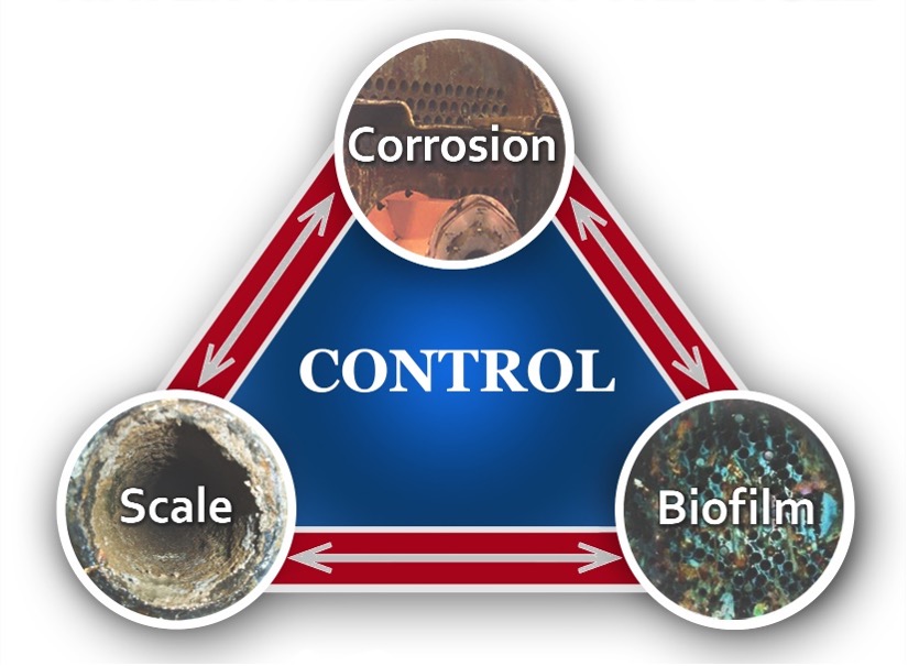
The focus of the previous installment was on cooling water microbiological fouling and control basics, as fouling can cause the most prompt and intense damage in cooling systems. However, scaling and corrosion can be problematic as well. Because scale and corrosion control programs often overlap, the next two installments will outline, respectively, primary scale-forming and corrosion mechanisms (scale formation in cooling water systems). We will tie these together in Part 5 when examining the evolution of scale/corrosion control programs.
In a recent report (2), Torbjörn Idhammar, President of IDCON, Inc., stressed the concept of Root Cause Problem Elimination (RCPE). This concept directly applies to the principles outlined in this series and in the previous series I wrote for Maintenance World regarding steam generation chemistry control. Preventive action is, almost without exception, much less costly than reactive maintenance. A primary point of this series is, “Evaluate and select the most effective programs to address RCPE from the start.” Then, have the instruments and trained personnel in place to regularly monitor system conditions to ensure that changes in water chemistry and physical properties are always accounted for.
The Impacts of Scale Formation and the Most Common Scaling Culprits
Critical factors for heat exchanger design include the type of exchanger, for example, shell-and-tube, plate-and-frame, etc.; unit size and dimensions; fluid properties and flow rates; and materials selection. Regarding the latter, the choice of metal(s) for heat exchanger tubes, plates, or other configurations is dependent on several factors, including durability and heat transfer properties. But while the heat transfer coefficients of common heat exchanger metals are somewhat variable, they are all much greater than deposits that can form due to poor water treatment.

This figure appeared in Part 2 of the series to emphasize the importance of microbiological control, but it also clearly illustrates the influence of even thin deposit layers on heat transfer efficiencies. Once formed, some deposits, and most notably the silicates, may be quite difficult to remove.
Some Scale Formation Basics
For decades, surface water supplies have been the makeup source for many cooling systems (although as fresh water becomes scarcer, alternatives are becoming more common). Table 1 offers a snapshot analysis of a lake in the midwestern United States that was built for power plant cooling and recreational purposes.

The unit milligram per liter (mg/L) is essentially equivalent to parts-per-million (ppm). The data is from a pristine water supply without high concentrations of mineral compounds. This is all well and good but consider if this water or similar supplies are “cycled up” in a cooling tower. (We examined cycles of concentration in Part 1 of the series.) The solubility factor of calcium and bicarbonate ions is very low, and if the solubility limit is exceeded, the following reaction will occur.
Eq. 1

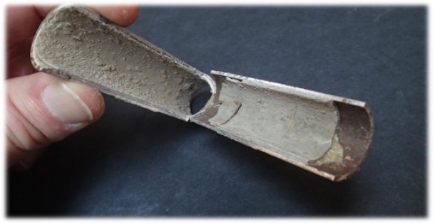
Figure 3 clearly illustrates calcium carbonate (CaCO3) deposition in an extracted heat exchanger tube.
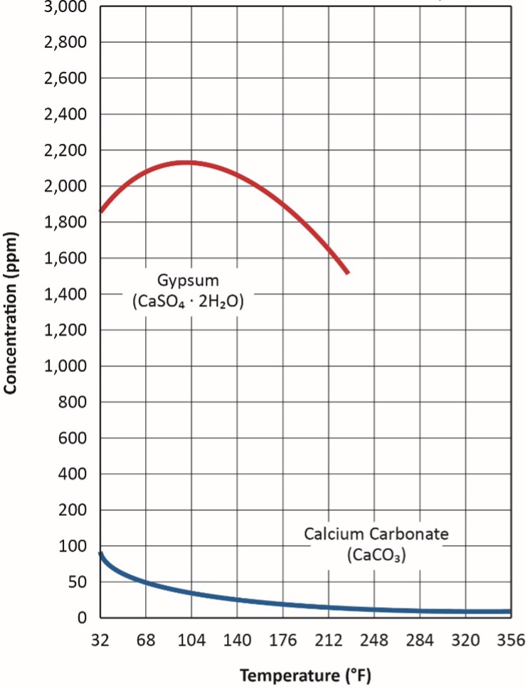
Another factor that influences this reaction is calcium carbonate’s inverse solubility. First consider an everyday example. I am not a coffee drinker but rather a tea drinker, in which I must have some sugar. In hot tea, the sugar dissolves with just a bit of stirring. Conversely, much agitation is required to dissolve sugar in ice tea. CaCO3 solubility is the opposite, and this peculiarity, along with that for gypsum, is shown in Figure 4.
Accordingly, for many applications, Equation 1 above can be modified to:
Eq. 2

The already low solubility of CaCO3 decreases with increasing temperature. An everyday example of this effect occurs in home plumbing systems, where hot water lines and showerheads can accumulate calcium carbonate scale (often incorrectly termed “lime deposits”). In a rather unique industrial example, at my first former power plant, all of the steam generators during my time there were on once-through cooling. All were equipped with biocide feed, but scale formation had never been a problem. In 1988, towards the end of an extended summer drought, condenser performance began to decline. Investigation revealed CaCO3 scale formation, where none had occurred before.
A review of in-house weekly lake chemistry analyses indicated that the dissolved solids concentration had increased four-fold. This phenomenon was akin to what conditions would have been normally if the condensers were serviced by a cooling tower operating at four cycles of concentration. The drought’s effect on lake water chemistry combined with the temperature increase in the condensers induced calcium carbonate scaling.
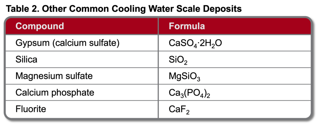
Other mineral deposits are possible in cooling systems. Table 2 outlines the most common but by no means all potential scale products.
As we will explore further in Part 5, in the middle of the last century a hugely popular treatment program for open-recirculating systems was sulfuric acid feed for scale control (to establish a typical pH range of 6.5-7.0) with feed of disodium chromate (Na2Cr2O7) for corrosion control.
However, in the 1970s and 1980s dawning recognition of hexavalent chromium (Cr6+) toxicity led to a ban on chromium discharge to the environment, which essentially eliminated chromate treatment for open cooling water systems. The replacement program was quite different, with a key concept being operation at a mildly basic pH (typically around 8.0 or perhaps a bit higher) to assist with corrosion control. A combination of inorganic and organic phosphates served as the core components of these programs, but this chemistry induced many cases of phosphate deposition in cooling systems. Program control, especially with variable water conditions, can be difficult. Also, concerns continue to grow about the influence of phosphate release to the environment. This issue is driving movement towards phosphate-free scale/corrosion control programs, to be addressed in Part 5.
Waters containing an appreciable amount of silica (SiO2) can present scaling problems when the water is cycled up in cooling towers. Silica can form deposits on its own, but as the pH rises above 8, the potential for magnesium and calcium silicate scaling greatly increases. Silica and silicate deposits are very difficult to remove, and as Figure 2 previously indicated, they are the most insulating of all deposits.
Conclusion
This installment presented fundamental information about scale formation in cooling systems. Because treatment methods are typically intertwined with corrosion control technology, we will examine control methods following Part 4 of this series, which will review primary cooling water corrosion mechanisms.
References
1) B. Buecker (Tech. Ed.), “Water Essentials Handbook”; 2023. ChemTreat, Inc., Glen Allen, VA. Currently being released in digital format at www.chemtreat.com.
2) https://www.idcon.com/resource-library/root-cause/cost-effective-rcpe/
3) Post, R., Buecker, B., and Shulder, S., “Power Plant Cooling Water Fundamentals”; pre-conference seminar to the 37thAnnual Electric Utility Chemistry Workshop, June 6-8, 2017, Champaign, Illinois.

Brad Buecker
Brad Buecker currently serves as Senior Technical Consultant with SAMCO Technologies. He is also the owner of Buecker & Associates, LLC, which provides independent technical writing/marketing services. Buecker has many years of experience in or supporting the power industry, much of it in steam generation chemistry, water treatment, air quality control, and results engineering positions with City Water, Light & Power (Springfield, Illinois) and Kansas City Power & Light Company's (now Evergy) La Cygne, Kansas, station. Additionally, his background includes eleven years with two engineering firms, Burns & McDonnell and Kiewit, and he spent two years as acting water/wastewater supervisor at a chemical plant. Buecker has a B.S. in chemistry from Iowa State University with additional course work in fluid mechanics, energy and materials balances, and advanced inorganic chemistry. He has authored or co-authored over 300 articles for various technical trade magazines, and he has written three books on power plant chemistry and air pollution control. He is a member of the ACS, AIChE, AIST, ASME, AWT, CTI, and he is active with Power-Gen International, the Electric Utility & Cogeneration Chemistry Workshop, and the International Water Conference. He can be reached at [email protected] and [email protected].
Related Articles
Proactive Maintenance for Hydraulic Cylinders


