Magnifying Mini: Microelectronics Miniaturization
Vadym Buyalsky
Microfluidics for Miniature Hydraulic & Pneumatic Drives
One of the most pervasive trends in fluid handling today is that of miniaturization. The call for smaller and smaller flow control devices is evident across the industry. Regarding hydraulic and pneumatic components specifically, the extraordinary mass-to-power and mass-to-response features of such technologies are enabling miniaturization.1 But as hydraulic and pneumatic devices continue to go mini, the manufacturing process has become more finite and certain design vulnerabilities have become more pronounced.
The intense development of microelectronics miniaturization has spurred development of the control part of electric-hydraulic or electric-pneumatic mini drive. The critical component of such a drive is the electric-hydraulic or electric-pneumatic control unit (CU) that interfaces the micro electronic control circuitry with the mini hydraulic or pneumatic actuating pilot of the control valve of that drive. Yet still, modern electric-hydraulic and electric-pneumatic mini drives represent only a scaled-down version of existing drives. And miniaturization efforts using current techniques have been limited in effectiveness because the smaller the parts are made, the more vulnerable they are to harmful external factors. Thus, the former imperfections of traditional electric-hydraulic and electric-pneumatic amplifiers (with moving mechanical parts) have been preserved. For example:
- Mini drives are susceptible to mechanical impacts and vibrations due to the decrease of mass of mechanical moving parts and the subsequent increase of their resonance frequencies.
- The electric and electronic elements of mini drives are vulnerable to extreme temperature, radiation, electro-static and magnetic fields, and corrosive gaseous or liquid chemicals.
In addition, changes in hydromechanical and aeromechanical parameters occur due to liquid and gas flows throughout the scaled down routes (channels, cavities, and other flow resistances).3 Manufacturing costs also increase, as it is expensive to produce micro-scaled parts that are accurate and uniform in surface roughness.
Thus, because of design vulnerabilities and manufacturing difficulties, the reliability of a micro-scaled CU with electrical circuitry and moving mechanical parts is of great concern to end-users.4 Addressing this issue calls for the creation of new embodiments of the CU on the basis of pure fluidic gas-to-liquid and liquid-to-liquid conversions. A CU with pure fluidic gas-to-liquid and liquid-to-liquid conversions enables a new type of miniaturized hydraulic or pneumatic drive that is reliable in severe conditions, including the influence of harmful factors and hazardous, potentially explosive environments. Further, this new type of drive can be used in parallel with traditional electric-hydraulic and electric-pneumatic miniaturized drives, namely in redundant trains of safety and security control systems of critical objects (e.g., nuclear power plants, mining equipment, industrial robots, etc.).
New Technology
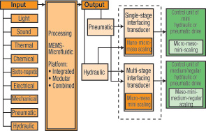
As is evident from traditionally accepted methods in the field of pneumatic and hydraulic fluidics, the output signal of any fluidic element is formed by the rearranged influence of high-impulse, jet-stream flow upon, at least, two intake channels.5 Until now, there have been different methods used to achieve angular deflection of high-impulse, jet-stream flow. However, all previous methods relied on the servo principle, where a very small amount of transverse energy is distributed or concentrated to impact the high-impulse, jet-stream flow, resulting in jet-stream flow angular deflection. However, new development in the area of microfluidics enables such a pure fluidic interface transducer (IT) that a weak hydraulic or pneumatic output signal from MEMS-Microfluidic Platform (MFP) can be converted into relatively powerful hydraulic input signal for the CU of a miniaturized hydraulic or pneumatic drive. As shown in Figure 1, the actual interfacing of the MFP with the CU through the IT improves the functional control abilities of the miniaturized hydraulic or pneumatic drive itself as it creates the possibility to operate the said drives through signals of different physical, biological, and chemical nature.
Since the different phases of fluid mediums (gas and liquid) are used in the interfacing process, the process must be steady-state for enabling the reliable and stable transfer of the hydraulic output signal from the IT to the input of the CU. The pure fluidic two-phase conversion detailed above offers a new method of gas-to-liquid and liquid-to-liquid conversion when performed with a properly rated I/O signal servo-amplification.
Figure 2 demonstrates the method of interface control of interacting flows (ICIF), which enables gas-to-liquid conversion. Under this method, the high impulse jet-stream flow J is caused by hydraulic supply pressure and goes out of nozzle 1 and continues its free flowing movement between the two parallel solid plane surfaces 10 and 11. The entire space between planes 10 and 11 is divided into two adjacent caves: first, the pneumatic control chamber with cavities L (left) and R (right), separated by the flow J (see section A-A); second, the hydraulic intake chamber, which contains at least two output channels (2 and 3 in this example) separated by sharp-edged splitter 4, as well as vent channels 7 and 8. The pneumatic control chamber is separated from the hydraulic intake chamber by solid partition, slotted with the channel (Ch) for left 5 and right 6 parts, arranged in full depth of the entire embodiment outline. The liquid jet-stream flow J is arranged to divide the inside space of pneumatic control chamber into two isolated cavities L and R where each of two free-side surfaces of said jet-stream flow J faces the adjacent pneumatic cavity and functions as an elastic movable wall of said cavity. The high-speed liquid jet-stream flow J entrains cocurrent flows of control gas through the cavities L and R, which ejecting phenomena is used for creating under-atmospheric pressure inside said cavities, hence converting each pneumatic cavity into a highly sensitive, pneumonic, two-port with elastic movable wall, where this wall is actually none other than said compact planar jet-stream flow J.
Optionally, control gas may be blown in cavities L and R in the form of compact gas stream flows (Gsf), coming alternatively, inside cavities L and R and impacting transversely free-side surfaces of jet-stream flow J, as if a properly high-impulse gas jet-stream flow might impact a flexible moving wall (Figure 2). Due to the ejecting phenomenon realized in this arrangement, there exits the possibility for digital control of this jet stream pneumatic/hydraulic amplifier (JPHA) only by closing alternatively one of the inputs of cavities L or R, while the inverse pneumatic input remains open into gas ambient. In accordance with the specific cocurrent flow control technique of the present arrangement, cocurrent gas flows do not mix with liquid flow J and do not interrupt free-side surfaces of flow J that are under stabilizing effect of surface tension, which acts also along the solid-to-liquid interfaces of all four soakage zones. The angle bending of high impulse compact liquid jet-stream flow J is made under influence of distributed or lumped impacting of control gas pressure differential. For example: ? p = pl – pr, where said jet-stream flow does not mix with surrounding control gas and the nearly parallelepipedic core 12 keeps its shape along the curved trajectory of flow J. Subsequent to flow J bending under control gas pressure ? p an output hydraulic pressure differential ?P = PR – PL is created due to the redistribution of high impulse of flow J between output hydraulic channels 2 and 3. Thus, the JPHA can operate either in analog or in digital modes with a few options of pneumatic output signal. Therefore, it may be used either in single-stage or in a multi-stage IT between the MFP and the CU of the miniaturized hydraulic or pneumatic drive (Figure 1).
In Figure 2, the procedure of transition of flow J from a depressurized or low-pressurized pneumatic control chamber in relatively high-pressurized hydraulic intake chamber comprises formation of locking fluid whirls 9 in gaps between each side-free surface of the planar jet-stream flow and adjacent inward side-solid surface of the jet-stream passing channel (Ch) so that said locking fluid whirls 9 are maintained at steady dynamic equilibrium in limits of hydraulically long jet-stream passing channel. The said locking fluid whirls are created by a liquid-gas mixture, which climbs upstream from the hydraulic intake chamber and attempts to enter the pneumatic control chamber under the effect of pressure difference between said chambers but is entrained back downstream by the jet-stream flow J entrapment. This phenomenon is kept at any static or dynamic status of transversely flexible planar jet-stream flow J (i.e., axial, or statically bent, or vibrating status).
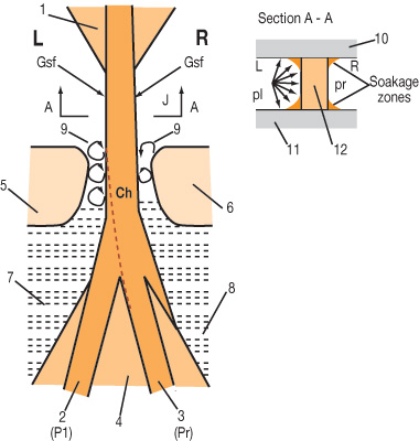
The said formation of locking fluid whirls is accomplished by the rated correlation of geometrical and hydraulic characteristics of the jet-stream flow J with geometrical shape and dimensions of the jet-stream passing channel (Ch), for example, by the rated correlation of Re number for flow J in pneumatic control chamber and Re number for flow J in jet-stream passing channel (Ch). If the speed of flow J does not exceed the value of approximately 3 mps (~ 9.84 FPS), the separation of the pneumatic control chamber from the hydraulic intake chamber is maintained by gas-to-liquid interfacing meniscuses, though in such case the outputs of JPHA would need an additional amplification for matching the CU inputs of the miniaturized hydraulic or pneumatic drive. The steady-state status of hydraulic differential output signal for ICIF methods is kept due to the facts that along all its free flow through the pneumatic control chamber of JPHA, the high-speed and high-impulse, jet-stream flow J does not mix with surrounding ambient gas, and locking fluid whirls 9 reliably isolate the pneumatic control chamber from the hydraulic intake chamber.
Figure 3 displays the method of attract-to-merge control of liquid jet-stream flow (AMC), which enables liquid-to-liquid and optionally gas-to-liquid conversion. The principle procedure of AMC conversion is illustrated by a typical arrangement of jet-stream hydraulic-hydraulic amplifier-converter (JHHA). So, the high-impulse free planar jet-stream flow J goes under hydraulic supply pressure out of nozzle 1 and continues its running between two parallel solid plane surfaces through the pneumatic control chamber L-R and through the jet-stream passing channel, outlined between solid partitions 2 and 3. Therefore, flow J enters the hydraulic intake chamber, which contains two output channels 4 and 5, each being aside a sharp-ended splitter 6, and vent channels 10 and 11. Flow J divides the pneumatic control chamber into two separate left (L) and right (R) cavities. The flow J creates under-atmospheric pressure inside said cavities L and R due to the described above injection phenomenon. The pneumatic control chamber is separated from the hydraulic intake chamber either by meniscuses 8 or by locking fluid whirls 9, depending on the speed value of flow J. The continuous or drop-shaped liquid control flow Cf goes over surface Scf of partition 2 towards the adjacent free side surface of flow J until it touches the later in point Attr, which lies on the geometrical bound 11 between pneumatic control and hydraulic intake chambers.
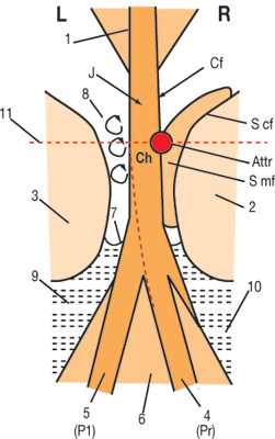
At that point there begins the merging of flows J and Cf. Meanwhile, flow Cf continues to run over surface Smf according to the Coanda effect. Since surface Smf is inclined at an acute angle to the neutral axis of flow J, the latter shall be inclined downstream at the same angle to the right, as it is shown in Figure 3. In the result of such attract-to-merge bending of flow J, its high-impacting impulse is rearranged between channels 4 and 5, and subsequent differential hydraulic output ?P = PR – PL is created. The flow J return in its neutral axial position must be accomplished by cancellation of the Coanda effect influence. This is accomplished either by admitting control gas into the engaged cavity or by breaking the running of continuous flow Cf, or both. While under the influence of control gas upon flow J inside one of the cavities another inverse cavity remains opened into a surrounded gas ambient, and during the ever one-sided action of control fluid flow Cf both cavities L and R of pneumatic control flow must be opened into a surrounded gas ambient. The steady-state status of hydraulic differential output signal for the AMC method is kept due to utilized technique, which ensures; 1) that neither high impulse jet-stream flow J nor low impulse (continuous or discrete drop-shaped) control liquid flow Cf mix with ambient gas along their free paths through the pneumatic control chamber; and 2) locking fluid whirls 8 reliably separate the unengaged cavity from the hydraulic intake chamber while the inverse cavity is locked by merged flows J and Cf.
The following techniques of fluid handling are utilized in initial experimental meso-scaled embodiments, arranged in accordance with the methods of beam deflection-type fluid amplifying described above:
Beam deflection-type servo control of high-impact free liquid flow by noninvasive and nondisturbing action in either angular contacting manner with at least one low-impact free liquid flow, or in manner of singular-side pressurizing the side-free surface of high-impact free liquid flow by distributed or concentrated control gas pressure.
Impact of high-speed jet stream flow on a solid barrier that contains intake hydraulic channels for sharing of the impact force of this flow.
Stabilizing influence of surface tension upon a free surface of flowing liquid at the interface of solid, liquid, and gas mediums.
Phenomenon of free-flow attraction to the juxtaposed solid surface (Coanda effect), where the free flow comes in contact with the solid surface due to the decreasing pressure between them as a result of ejection effect presence.
The phenomenon of attract-to-merge joining of adjacent free liquid mediums, moving as a steady-state flow in ambient gas between at least two parallel solid surfaces, where there is only one point of contact shall result in: 1) the subsequent merging along the entire flow due to the influence of surface tension, and 2) the deflection of high-speed impacting liquid flow towards the slow-speed control liquid flow due to the continuity of flow, provided this slow-speed flow runs outwards of the high-speed flow along the attracting solid surface, in compliance with Coanda effect.
These effects enabled the relevant use of mathematical relations from classical hydromechanics that in turn provide the possibility of rated initial prototyping.
Applications & Benefits
This new method (patent pending), it is believed, will have a dramatic impact on the next generation of hydraulic and pneumatic drive controllers. This will be achieved first in the effective miniaturization in the micro/meso scale, and secondly, in the reduction of external influences from heat fluxes, high temperature fields, magnetic, and radiation fields based on the fact that the IT (in the embodiments of JPHA and JHHA) will have no moving mechanical parts or electrical components inside. One of the first uses could be as an actual bridge from nano-to-micro scaled microfluidic platforms to the miniaturized meso-scaled or standard macro-scaled hydraulic and pneumatic drives. This new technology will be of interest to markets such as industrial, medical, aviation, space, and defense. Use in robotics, UAV’s, and nuclear controls are just a few applications. The size and scope of the market potential for this new technology is currently limited only to the size of the current market where hydraulic and pneumatic drives are used today. In the future, new markets may also open due to the size, nature, and other benefits of the technology. By allowing the production of mini drives with no moving parts, the technology described above will enable miniaturization without an increase in manufacturing cost. As the concept expands to all levels of controls, opportunities to retrofit legacy equipment may turn up, driven by environmental, health, security, and safety issues.
Indeed, all areas of hydraulic and pneumatic drives will benefit from this new approach, provided there is a purposeful speed-up in development and lot production of microfluidic modular assemblies (MiFluMA) that consist of the MFP, IT, and CU of miniaturized hydraulic or pneumatic drives.
References
Andrew E. Parr, “Hydraulics and Pneumatics: A Technician’s and Engineer’s Guide,” 2nd ed., Butterworth-Heinemann, pg. 244, 1998.
Moog Inc., “Servo-Valves,” Catalog: 2004.
Chin-Ming Ho and Yu-Chong Tai, “Micro-Electro-Mechanical-Systems (MEMS) and Fluid Flows,” Annual Review of Fluid Mechanics, Jan. 1998, Vol. 30, pg. 579-612.
Jiantao Pan, “MEMS and Reliability,” Dependable Embedded Systems, Spring 1999, Carnegie Mellon University, 18-849b.
Flueric gas-to-liquid interface amplifier. Inventor: Robert L. Woods. U.S. Patent #3,811,475. May 21, 1974.
Vadym Buyalsky, Ph.D., has over 30 years of experience in fluidics and microfluidics. He has written 75 scientific works and papers and holds 27 patents. He was the executor of nine science and research programs in Ukraine, Russia, and the former Soviet Union. He also served as a Fellow of Scientific Councils for Object “Shelter” at the Chernobyl Nuclear Power Plant and the Kiev Civil Aviation University. Dr. Buyalsky is currently a member of the research and development team for CTRL Systems Inc., a provider of solutions for nondestructive testing and flow control. He can be reached at vbuyalsky@ctrlsys.com or 410 876-5676.
Related Articles

The Benefits of a Modern CMMS for Solar Power Farms

The Hidden World of Data Management

How to Mitigate Risk with Your Mobile Solution Proof of Concept

Reliability Strategies Function for MAS 9.0 (MAS RS)

Managing an EAM / CMMS Selection

Sources of data for AI Empowered Maintenance – Manufacturing Execution System