Understanding The Basics of Balancing & Measuring Techniques
Gary K. Grim & Bruce J. Mitchell VibrAlign
Why Balance? All rotating components experience significant quality and performance improvements if balanced. Balancing is the process of minimizing vibration, noise and bearing wear of rotating bodies. It is accomplished by reducing the centrifugal forces by aligning the principal inertia axis with the geometric axis of rotation through the adding or removing of material. In order to understand the basics of balancing it is necessary to define the following fundamental terms.
Fundamental Terms
Center of Gravity (C.G.)
When a is the acceleration due to gravity, the resultant force is the weight of the body. For this reason the term center of gravity can be thought of as being the same as the center of mass. Their alignment would differ only in large bodies where the earth’s gravitational pull is not the same for all components of the body. The fact that these points are the same for most bodies, is the reason why static (non-rotating) balancers, which can only measure the center of gravity, can be used to locate the center of mass. Additional information on static balancers will be reviewed in the following pages.
Center of Mass
The center of mass is the point in a body where if all the mass was concentrated at one point, the body would act the same for any direction of linear acceleration. If a force vector passes through this point the body will move in a straight line, with no rotation. Newton’s second law of motion describes this motion as F = ma. Where the sum of forces, F, acting on a body is equal to its mass, m, times its acceleration, a.
F=ma
Geometric Axis
The geometric axis is also referred to as the shaft axis or the engineered axis of rotation. This axis of rotation is determined either by the rotational bearing surface, which exists on the work piece, or by the mounting surface. An adequate mounting surface establishes the center of rotation at the center of mass plane (the plane in which the center of mass is located).
Principal Inertia Axis
When a part is not disc shaped and has length along the axis of rotation, it spins in free space about a line. This line is called the principal inertia axis. The center of mass is a point on this line. It takes energy to disturb a part and cause it to wobble or spin on another inertia axis. Examples of this would be a correctly thrown football or a bullet shot from a rifle. When the principal inertia axis coincides with the axis of rotation the part will spin with no unbalance forces. In this case the static as well as the couple unbalance are equal to zero.
In summary, a state of balance is a physical condition that exits when there is uniform total mass distribution. Static balance exists when the center of mass is on the axis of rotation. Whereas, both static and couple balance exist when the principal inertia axis coincides with the axis of rotation.
Types of Unbalance
The location of the center of mass and the principal inertia axis is determined by the counter balancing effect from every element of the part. However, any condition of unbalance can be corrected by applying or removing weight at a particular radius and angle. In fact the amount of unbalance, U, can be correctly stated as a weight, w, at radius, r.
U=wt
Static unbalance can also be determined if you know the weight of the part and the displacement of the mass center from the geometric axis. In this case, U, is equal to the weight, w, of the work piece times the displacement, e.
U=we
Static Unbalance
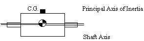
Is a condition that exists when the center of mass is not on the axis of rotation. It can also be explained as the condition when the principal axis of inertia is parallel to the axis of rotation. Static unbalance by itself is typically measured and corrected on narrow disc-shaped parts, such as a Frisbee. To correct for static unbalance requires only one correction. The amount of unbalance is the product of the weight and radius. This type of unbalance is a vector, and therefore, must be corrected with a known weight at a particular angle. Force unbalance is another name for static unbalance.
As discussed earlier, a workpiece is in static balance when the center of mass is on the axis of rotation. When this condition exists, the part can spin on this axis without creating inertial force on the center of mass. Parts intended for static applications, such as speedometer pointers or analog meter movements, benefit from being in static balance in that the force of gravity will not create a moment greater at one angle than at another which causes them to be non-linear. The following drawing represents an example of static unbalance.
Couple Unbalance
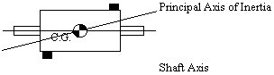
Is a specific condition that exists when the principal inertia axis is not parallel with the axis of rotation. To correct couple unbalance, two equal weights must be added to the workpiece at angles 180° apart in two correction planes. The distance between these planes is called the couple arm. Couple unbalance is a vector that describes the correction. It is common for balancers to display the left unbalance vector of a couple correction to be applied in both the left and right planes.
Couple unbalance is expressed as U = wrd where the unbalance amount, U, is the product of a weight, w, times the radius, r, times the distance, d, of the couple arm. Couple unbalance is stated as a mass times a length squared. Common units of couple unbalance would be g-mm2 or oz-in2. The angle is the angle of the correction in the left plane. (Please note: In mechanics, the angle is perpendicular to the plane of the radius vector and the couple arm vector. This is an angle 900 from the weight location.) Couple unbalance can be corrected in any two planes, but first the amount must be divided by the distance between the chosen planes. Whereas static unbalance can be measured with a non-rotational balancer, couple unbalance can only be measured by spinning the workpiece.
A combination of force and couple unbalance fully specifies all the unbalance which exists in a part. Specifying unbalance in this manner requires three individual correction weights. The following drawing represents an example of couple unbalance.
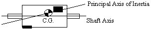
Two Plane Unbalance
Is also referred to as dynamic unbalance. It is the vectorial summation of force and couple unbalance. To correct for two plane unbalance requires two unrelated correction weights in two different planes at two unrelated angles. The specification of unbalance is only complete if the axial location of the correction planes is known. Dynamic unbalance or two plane unbalance specifies all the unbalance which exists in a workpiece. This type of unbalance can only be measured on a spinning balancer which senses centrifugal force due to the couple component of unbalance.
Dynamic Balancing
Is a term which specifies a balancer that spins and measures centrifugal force. It is necessary to use this type of balancer when measuring couple or two plane unbalance. Typically it can also be used to provide greater sensitivity to measure static or force unbalance. The following drawing represents an example of dynamic unbalance.
Units of Unbalance
Unbalance can be specified as the weight of mass to be added or removed at a correction radius. The weight units can be any convenient units of measure which take into account the weighting equipment available and the size of the whole unit of measure. Grams (g), ounces (oz), and kilograms (kg) are the most common units. Occasionally Newton’s (N) are specified, but for practical use must be converted to available weight scale units. Length units usually correspond to the manufacturers standard drawing length units. Most commonly these are inches (in), millimeters (mm), centimeters (cm), and meters (m). The most common combinations used to specify unbalance are ounce-inches (oz-in), gram-inches (g-in), gram-millimeters (g-mm), gram-centimeters (g-cm), and kilogram-meters (kg-m).
Motion of Unbalanced Parts
What is the effect of unbalance on a rotating part? At one extreme, if mounted in a rigid suspension, a damaging force must exist at support bearings or mounting surface to constrain the part. If the mount is flexible, the part and mount will exhibit significant vibrations. In a normal application, there is a combination of both.
Consider an unbalanced thin disc mounted on a simple spring suspension. The spring will respond differently depending on the speed at which the disc rotates. At very low speeds (less than one half the resonant frequency of the spring mass) the unbalance of the disc generates very little centrifugal force, causing a small defection of the spring and a small motion of the mass.
With rigid bodies the unbalance remains the same although an increase in speed causes an increase in force and motion. Force increases exponentially as the square of the change in speed. Twice the speed equates to four times the force and four times the motion. In other words, force is proportional to the square of the rotating speed. An equation for estimating force is:
F=1.77U(rpm/1000)2
Centrifugal Force
| Centrifugal force caused by 0.001 oz-in of unbalance at various speeds. |
The centrifugal force of the unbalance is outward from the center of the part, at the location of the weight. In a hard suspension balancer the force bends a rigid spring causing the high spot of vibration to occur at the location of the weight.
At speeds twice or greater than the resonant frequency of the spring-mass, the unbalance force is much greater than the spring force. The motion of the unbalanced part is limited by its own inertia. The part rotates about the present center of mass at any running speed in this range. Displacement peak is equal to the center of mass eccentricity, e, and therefore Xp = e. The formula for displacement peak, Xp, is Unbalance, U, divided by the part weight. (Note: the weight units of unbalance must be the same as part weight units.) In a balancer this would be termed a soft suspension.
Xp=U / weight of the part
At remaining speeds near the resonant frequency, the amplitude of motion can get much larger than at higher speeds even if the unbalance force is less. The resonance exists when the resisting force of the part inertia is equal to and opposed to the resisting spring force. The only resisting force is due to mechanical damping. When the damping is low, the amplitude of vibration may be fifty times greater at resonance. In the past some balancing companies ran their balancers at this speed to gain sensitivity. However, with the great improvements of present day electronics, this range of speed is considered unpredictable and is therefore typically avoided.
A part other than a thin disc, which has length along the rotating axis, has a similar response when rotated supported in a suspension system at each end. With speeds below resonance (in a hard suspension), the force generated by centrifugal force divides between the two suspension points just as a simple static load divides between two fulcrum points. With speeds above resonance (in a soft suspension), the part spins, not only about the center of mass, but also about the principal inertia axis. The peak displacement at any point along the part equals the distance between the principal inertia axis and the geometric axis. It should be noted that there may be several resonance speeds. Resonance of the total mass on a spring system will cause the part to translate. At a different speed, the part rotational inertia and spring system will cause it to rotate about a vertical axis. This is another reason to avoid this range of running speed.
Balancing Equipment
Static Balancers
Static balancers do not rotate the part in order to measure unbalance. Instead, their operation is based on gravity generating a downward force at the center of gravity. An example of and older form of static balancer is a set of level ways. Although extremely time consuming, this old method is still effective at minimizing static unbalance. The force downward on the center of gravity will cause the part to rotate until the C.G. is directly below the running surface, which identifies the location of the heavy spot. Typically with level way balancing the unbalance amount is not known and the part is corrected by trial and error until the part no longer rotates. However, it is possible to measure unbalance amount on a level way balancer. This is accomplished by rotating the heavy spot up 90°, and then measuring the moment of torque. Historically, this was often achieved by using a hook scale to determine force at a known radius.
Modern static balancers measure parts with the parts rotational axis in a vertical orientation, directly over a pivot point. This type of gage can quickly sense both amount and angle of unbalance. Gravity acting on an offset center of mass creates a moment on the part which tilts the gage.
Static balancers can be divided into two types depending upon how they react to this unbalance moment: those with a free pivot where the amount of tilt is measured as a direct indication of the amount of unbalance, and those that restrict amount of tilt and measure the moment of unbalance.
Static balancers which have a free pivot offer no resistance to the downward force of gravity on the C.G. It is necessary that the C.G. of the workpiece and tooling together be a proper distance below the pivot point. The distance the C.G. is below the pivot point determines the sensitivity of the balancer. This distance is often set up by an adjustable counterweight connected to the tooling below the pivot. With no part on a leveled set of tooling, the C.G. initially is directly below the pivot point. When an unbalanced part is placed on the tooling it causes the C.G. to raise and shift away from the center in the direction of the unbalance. Moment caused by the gravity on the new C.G. causes the tooling to tilt, until the new C.G. is directly below the pivot. As it tilts the moment arm and, consequently, the moment, are reduced to zero. The amount of tilt is determined by measuring the distance between an arm extending from the tooling and the machine base. The amount of tilt is proportional to the amount of part unbalance.
Measuring unbalance on a static balancer is most often achieved with two LVDT’s oriented at 90° to each other. A typical pivot consists of points in a socket, ball on an anvil, a small diameter flexure in tension, hydraulic sphere bearings, and air sphere bearings. Each have problems associated with keeping the pivot free. The mechanical point contact system must be mechanically protected to prevent flat spots on the ball, or a point of indentation in the anvil. The wire flexure can be bent or broke if not protected. The sphere bearings must be kept perfectly clean to prevent drag. Two additional concerns are that the sensitivity is dependent upon the weight of the part and the pivot must be well protected to prevent damage that can effect balancer performance.
There is however a better alternative that overcomes these problems, it is called the stiff pivot balancer. With this type of balancer the pivot is a post which acts as a stiff spring. The moment due to unbalance bends the post a small amount and the tilt is measured to determine the amount of unbalance. With a stiff pivot balancer the calibration is not effected by part weight and the balancer is accurate, simple, and extremely rugged.
Dynamic Balancers
The previously described static balancers depend totally upon the force of gravity at the C.G. As a result, with a static balancer, it is not possible to sense the couple component of unbalance. To sense couple unbalance the part must be spun. Such a balancer is termed a centrifugal or dynamic balancer. Dynamic balancers consist of two types: soft suspension and hard suspension.
The most common dynamic balancers fixture the workpiece with the shaft axis horizontal. There are, however, both soft and hard bearing vertical balancers too.
Soft Suspension Dynamic Balancers
Are also referred to as a soft bearing balancers. The soft suspension balancer operates above the resonant frequency of the balancer suspension. With this type of balancer the part is force free in the horizontal plane and rotates on the principal inertia axis. The amplitude of vibration is measured at the bearing points to determine the amount of unbalance. There are problems in using the measured information to correct the balance of the part. Each individual part has its own calibration factor and crosstalk of correction information. Stated in a different way, if a balanced part has one unbalance weight added in one correction plane, the information necessary to predict the new line of the principle inertia axis is not available. One weight causes vibration at both suspensions and the amplitude and ratio of these two vibrations is not known. When the influence of a weight in a second plane is added, it is not possible to separate the information on the two weights.
To determine the calibration and crosstalk factors, trial weights must be added individually in each plane, and the reaction measured. When using an unbalanced part the effect of initial unbalance must be removed from the trial weight measurements. When these factors have been determined, each channel reads out only the unbalance in the corresponding correction plane. These two channels then have what is called plane separation. The main disadvantage of soft suspension balancers is the requirement of extra setup spins for the calibration of different size and weight workpieces.
Dynamic Hard Suspension Balancers
Are also referred to as a hard bearing balancers. The hard suspension balancer operates at speeds below the suspensions resonant frequency. The amplitude of vibration is small, and the centrifugal force generated by the unbalance is measured at the support bearings. With a hard suspension balancer it is only necessary to calibrate the force measurement once. This one time calibration is typically performed by the balancer manufacturer at their own facility.
Using the force measurement and an accurate speed measurement, the balancer electronics can calculate the corrections which are required at the support bearing planes. However, since corrections cannot be made at the bearing planes, the unbalance information must be translated to the two correction planes. For the calculation, the location of the correction planes relative to the bearing planes are entered by the operator when the balancer is set up for a particular part.
In addition to the advantage of being inherently calibrated, hard suspension balancers are: easier to use, safer to use, and provide rigid work supports. With hard suspension balancers it is possible to provide hold-down bearings to handle the negative load which can be generated when a part is run outboard of the two support bearings.
All of the balancers described are implemented with analog electronics. However, the basic calculations required for plane separation and plane translation require complicated circuits, which in turn require trimming and setup. Computer electronics are ideally suited to these applications. In addition computer electronics can memorize part setups for easy recall, collect unbalance data, provide statistical information, and output the data to a printer or disk drive.
Summary
Virtually all rotating components experience significant quality improvements if balanced. In today’s global market consumers look for the best products available for their money. They demand maximum performance, minimum size, and lower cost. In addition everything must be smaller, more efficient, more powerful, weigh less, run quieter, smoother and last longer.
As consumer demands continue to increase, balanced components will remain an essential ingredient. Balancing will always be one of the most cost effective means of providing quality products to consumers.
Related Articles
Infrared Thermography

Making the Case for Harmonics, Part 2

Integrating Vibration and Wear Debris Analysis for Machine Condition Monitoring

Coal Plant O & M: Condition Monitoring Cuts Mirant Mid-Atlantic’s Costs

The Interplay of Smart Manufacturing Technologies: IIoT, Industry 4.0, and AI