Ultrasound for Better Lubrication
Practicing Oil Analysis, Benjamin Fried, CTRL Systems Inc.
A manufacturing facility had two identical eight-inch bearings on a machine. The maintenance technicians knew that one was causing a problem with the machine’s operation, as well as compromising the quality of the product. An ultrasonic sensor, the CTRL UL101, was used to listen to both bearings. One bearing sounded like it was operating properly, but the other produced no sound. Suspecting over lubrication, half the grease was drained from the bearing that produced no sound. The ultrasonic sensor was used to monitor the bearing while it was being lubricated until it sounded like a normal bearing. Once properly lubricated, the equipment began operating perfectly. This is a prime example of how ultrasound technology can be used for better lubrication.
Ultrasonic technology (UT) has become widely accepted for the detection of leaks in both pressurized and nonpressurized systems. Most compressor service companies and several manufacturers own some type of ultrasonic sensor for pinpointing leaks. It is easy to cost-justify the purchase of an ultrasonic sensor based upon the high cost of energy loss due to leaks. However, there is another application for ultrasound that consumers, nondestructive testing (NDT) organizations, and even developers and manufacturers of ultrasonic sensors are often not aware of or overlook. UT can be used as a means to detect early wear of components such as bearings and gears due to lack of lubrication or overlubrication.
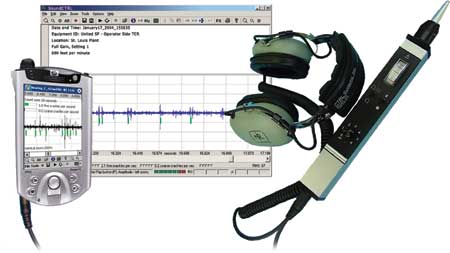
Ultrasonic Technology for Lubrication Millions of dollars are spent each year by organizations to monitor critical components of equipment used for production. Preventive maintenance (PM) is widely accepted to help prevent untimely shutdowns and to extend the expected lifespan of bearings and gears. The limitation of a PM program is that it is subjective and largely dependent upon the expertise of the technician. A typical PM may require a technician to “visually inspect the bearing for signs of wear” or “apply one half shot of grease.” Although these actions are helpful and even necessary, they are not 100 percent effective and are limited in their usefulness to improve production.
Improvements to ultrasonic sensors in the past couple years have enabled organizations to expand their monitoring practices. Increased sensitivity allows today’s sensors to detect smaller signals. This enables the user to detect smaller flaws and detect them even earlier. Small pieces of grit in lubrication, for example, will be detected by the sound of impact against the rollers of a bearing. Better selectivity helps diminish ambient noise or decrease white noise. Analysis and quantification is made easier when the source signal of a bearing being monitored can be distinguished from nearby components. Also, once white noise is diminished, the quality of the signal is improved and is better served for analysis. As a bearing begins to wear or lubrication becomes less effective, the ultrasonic signature will increase in amplitude and flaws will become apparent.
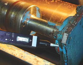
How Ultrasonic Technology Works Sound is caused by friction, impact, turbulence and electrical discharge. When two objects are rubbed together, they produce friction. Not only does friction cause sound, but it also causes heat. Generally speaking, the more friction there is, the more sound and heat produced. As a component, such as a bearing, heats up, it expands. At some point, it will expand too much and seize up, causing the equipment to fail and production to cease. Also, when there is a lot of friction, particles from each component tend to be scraped off. Oil is used to lubricate bearings so that friction is reduced, but as a bearing gets older, it becomes rougher.
Impact is nothing more than a moment of friction. As gears rotate, the cogs interlock. The brief interlocking causes impact, which produces sound. Turbulence is produced by gas leaks. As gas escapes from one pressure system into another, the molecules tumble out. In the case of a vacuum leak, the molecules tumble in. Likewise, electrical discharge excites the molecules in the air. Once excited, the turbulent behavior of the molecules produces sound.
When sound is produced, waves of different frequencies will travel from the source in all directions. The distance the sound wave travels and the amplitude depend upon the amount of energy transferred from the source and the frequency of the wave. Lower frequency sounds travel much farther than high-frequency sounds. Earthquakes produce low-frequency sounds. An earthquake in California can produce a wave that travels through the earth’s crust and can be detected in Japan. Some animals, such as bats, produce high-frequency sounds that do not travel far. These sounds are used to detect small objects, such as insects, from close distances.
In each of the previous cases mentioned, the human ear cannot hear these sounds. They are out of the range of normal human hearing, which means they are below 20 hertz and above 20 kilohertz. Ultrasonic sensors use microphones that detect sound at a frequency about 40 kilohertz, which is well above the human range of hearing. The received ultrasound is then converted or stepped down into an audible range and output to headphones for listening or to a computer for analysis.
By listening to components at the 40 kilohertz range, subtle events can be detected, such as small scratches on the race of a bearing or a piece of grit in the lubricant. As a bearing or gear rotates, the scratch or piece of grit produces impact that is detectable only in the ultrasonic range. Furthermore, the wave produced in the 40 kilohertz range does not travel far from the source. Therefore, when listening to a bearing in contact mode, sounds from other nearby components do not interfere. This prevents misdiagnosis and provides the ability to quickly pinpoint the real problem.
In one such case, a United States Navy ship participated in a series of onboard tests with ultrasonic technology to evaluate the potential benefit of its implementation in several areas. During the tests, the crew from another ship asked about the ability of the technology to identify internal pump problems. The electric main lube oil pumps were not putting out sufficient pressure. The ship was fast approaching a deployment, and the crew could not determine the root cause of the loss of pressure for the pumps with other technologies. The CTRL UL101 ultrasonic inspection system and SoundCTRL were used to test the pumps. Of the four pumps, it was discovered that one of the pumps was bad, producing an abnormal amount of ultrasound, and another was suspect. The pumps were dismantled and opened, and inspection revealed that one pump had damaged components and the other pump was binding.
What to Look For in an Ultrasonic Sensor Ultrasonic sensors used for leak detection and mechanical analysis typically use a piezoelectric microphone with center of frequency of 40 kilohertz to receive the sound wave and convert it into an electronic signal. Prices range quite radically for the different sensors, but there are three ranges of prices to consider. The low range includes sensors that cost from approximately $100 to $1,000. The middle range has sensors from $1,500 to $4,000. The upper range can cost as much as $10,000.
Many low-range sensors are advertised in catalogs and are often strictly used for leak detection. Most use a volume control dial that simply adjusts the volume of the converted audible signal, but does not adjust the sensitivity. These sensors are often sold with few attachments or none at all.
Sensors in the high price range are the same as midrange sensors but with add-on software. The software is attached to the sensor for recording and/or analyzing the signal output. Software used for analyzing ultrasonic signals may have several features such as the ability to record the actual signal, record some type of signal average, calculate the average amplitude often using a root mean squared (RMS) method, flag anomalies, and store equipment and maintenance routes.
Sensors in the middle price range combine features and functionality of both the low- and high-range sensors. Some of these sensors have volume control. Some have sensitivity adjustment. It is important to distinguish between the two. Sensitivity control is necessary for detecting weaker signals from greater distances. It is also necessary to minimize the amount of ambient ultrasound that could interfere with the diagnosis of bearings, gearboxes and valves.
Frequency adjustment is another important feature to consider. The center of frequency of each microphone is 40 kHz. Adjusting away from 40 kHz minimizes the ability of the sensor to distinguish the signal from white noise; therefore it is not recommended.
Sensors may also include a digital meter or an analog meter. A digital meter will use a relative number, even decibels, to indicate the peak level of ultrasound detected. Analog meters are used to indicate the overall characteristics of the sound and are much more sensitive for the detection of small irregularities. Analog meters are also much more indicative of the random noise produced by equipment and consume far less power.
Some other features of ultrasound equipment to consider include the design of the sensor for fitting in hard-to-reach areas and the material used to make the sensor. If used in harsh environments, a plastic sensor or one that is poorly manufactured may not last long. Battery usage is also a consideration. …
… Rechargeable batteries can be expensive and do not last much more than a shift or two. A nine-volt battery should be able to operate the ultrasonic sensor for several shifts, at least. Additionally, some manufacturers offer devices that have been manufactured according to intrinsically safe standards. These sensors should come with a certificate of conformance, verifying that they may be safely used in hazardous environments.
Warning signs of problems relating to lubrication can be subtle but critical. Lubricant is used to decrease friction of components. If a component is underlubricated, the level of friction and sound will increase. If the component is overlubricated, there will be little-to-no sound produced at all.
Such subtle changes will be detected only with a sensitive sensor with a large signal-to-noise ratio (SNR). Every electrical component produces some small amount of noise when working. The sensor should be able to distinguish this “white” noise from the input signal. If there is too much white noise, analysis is not possible. Additionally, too much white noise can dampen the input signal, making it undetectable. It is important to make sure the test system is adequate for the applications before it is purchased.
How to Incorporate UT into an Effective PdM Program To obtain the full benefits of UT, it is important to select the right sensor for the lubrication program. It is even more important to spend the right time and energy implementing the ultrasonic technology correctly. Most UT companies will work with the customer to develop an effective turnkey program.
The first step in developing a program is to become familiar with the characteristics of ultrasound, the ultrasonic sensor and the software. Most companies offer some sort of product and technology training. It is best to have on-site training so that the individuals who will be using the equipment can gain some immediate insight and the trainer can learn more about the maintenance department’s goals and challenges.
The second step is to identify the critical components or areas where ultrasound will be used. There are thousands of places to use ultrasound, and it can be overwhelming to do everything at once. However, it is usually just a few components that cost an organization the most money. If an oil analysis program is already in place, those components that have been frequently identified as having problems should be the first ones to be included in the ultrasound program. Ultrasound can be used to identify the causes of the problems, such as poor installation or misalignment.
Third, it is important to develop an inspection schedule that meets the organization’s needs but does not put too much burden on the maintenance staff. It is vital to monitor the identified components on a regular basis, such as twice per week. Once baselines are established, large changes in the ultrasonic signal will indicate changes in the operation, lubrication and condition of the component.
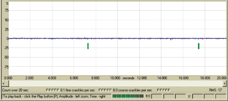
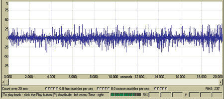
For example, a normal bearing typically produces a soft, whirring sound and a relatively even wave form when viewed with analysis software (Figure 1).
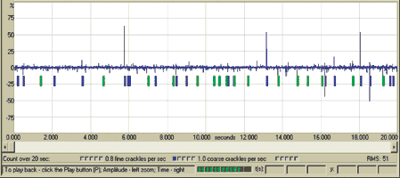
If a bearing is damaged, intermittent pops or grating may be heard, depending on the rotation of the bearing and the degree of damage. Analysis system software will reflect a heightened crackle count, and abnormal spikes in the waveform will be visible (Figure 2).
If a bearing is underlubricated, there will be an increased sound of friction. The sound intensity of the bearing will increase, and it will emit an intense scraping sound. The root mean squared (RMS) value of the signal will also increase, and the height of the waveform will visibly increase (Figure 3).
Finally, the technician’s recordings and notes should be reviewed. Ultrasound is instantaneous; with the right sensor, an experienced technician will detect lubrication problems right away. The latest changes in ultrasonic sensors will further enhance the user’s ability. The most effective program will also consist of comparing record history for critical components obtained from several different technologies and programs including oil analysis, ultrasound and preventive maintenance.
Once properly implemented, ultrasonic technology will decrease the costs of maintenance and production, increase safety standards, and increase quality control. In other words, your organization will run a lot smoother.
Editor’s Note Benjamin Fried is employed by CTRL Systems in the product development and support division. For more information about ultrasonic technology and turnkey implementation, contact CTRL Systems at 877-287-5797. Additional resources such as test techniques, frequently asked questions and multimedia clips that demonstrate the characteristics of various component conditions are available at www.ctrlsys.com.
Please reference this article as: Benjamin Fried, CTRL Systems Inc., “Ultrasound for Better Lubrication”. Practicing Oil Analysis Magazine. November 2004
Related Articles
The Lubrication Requirements of Couplings

The Building Blocks to Creating an Effective Lubrication Program

Does Lubrication Belong in the CMMS?

Water Contamination

Top Ten Ways Not to be World Class at Machinery Lubrication


