

How to Build Walkways and Platforms
Mike Sondalini, PWW EAM System Consultant
with permission of BIN95 Business Industrial Network
Posted 9/8/26
INTRODUCTION HOW TO BUILD WALKWAYS AND PLATFORMS
Walkways, platforms, stairs, and ladders play a critical role in providing safe access to equipment, work areas, and elevated structures. To ensure safety and long-term reliability, these access systems must be properly designed, constructed, and installed to accommodate expected loads, environmental conditions, and user requirements.
This quick guide to how to build walkways and platforms outlines the key requirements for designing and building access structures, including material selection, load capacities, acceptable deflection limits, and the specific criteria for stairs, ladders, guardrails, and structural connections. Following these principles helps create safe, durable access systems that support both personnel and operational needs.
Unless a structure meets this standard*, it could be considered unsuitable and may need to be rebuilt. The standard specifies when and what type of access structure to use depending on the slope needed for accent. Figure 1 shows the allowable angles for the types of access.

Stairs, walkways, platforms and ladders can be made from timber, aluminum, concrete, masonry or steel. Each material has characteristics and limitations that must be accommodated in the design of the structure.
ALLOWABLE LOADS
The standard sets the allowable loads for floors on walkways and platforms as the dead weight load of the structure plus a live load of 250kg/sq. m or a 100kg load at any point, whichever produces the worst deflection. If the loads are higher than this then AS 1170 Part 1 – Dead and live load combinations – is to be used.
The weight of an 80kg person carrying a toolbox will be close to the allowable live loads for walkways and platforms. If equipment is also to be mounted on the platform, then a thorough engineering design will be needed. Wind loads are added to the weight loads when sizing the members.
The guard rails around walkways and platforms are required to handle a 55kg point load or a 33kg per meter load, whichever produces the worst deflection, applied at any position or direction on the top rail.
ACCEPTABLE DEFLECTIONS
The allowable loads carried by walkways and platforms must not over stress the materials used in its construction. For steel walkways and platforms a rule-of-thumb is to limit the maximum deflection along a span to
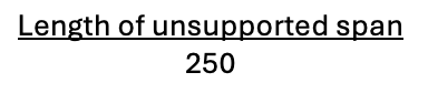
This represents a 10mm deflection per 2.5 meters. The overall deflection for a span should be kept to a maximum of 10mm – 15mm. Greater deflections scare people and they will consider the structure unsafe, though it is unlikely to be.
The allowable deflection can be used to select steel members. By putting a length of structural steel between supports spaced a span apart and loading the steel member at the center with its maximum load, you can use the 10mm deflection criteria to check the steel beam’s strength. Once the whole structure is fabricated it will be stiffer and will deflect less than the individual members selected this way.
REQUIREMENTS FOR STAIRS
Stairs are safer to use than ladders but expensive to make. Stairs are used where much traffic will pass over the walkway or platform or a safe and quick access is required.
The length of a stair is limited to 18 rises after which a landing is required. A change of direction is needed every 36 rises to prevent a person falling further unless the landing is more than two meters long. The width of a stair is to be a minimum of 600mm between the inside edge of the handrail.
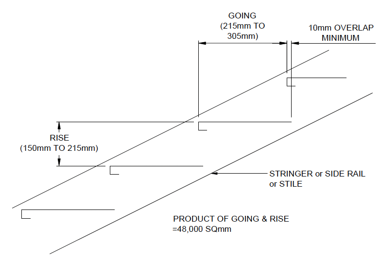
The angle of the stairs is limited to a range of allowable goings and rises. The rise must be between 150mm and 215mm with the going between 215mm and 305 mm and the multiplication of the rise and going in millimeters must be between 45,000mm2 and 48,000mm2. Figure 2 shows the necessary tread requirements for stairs.
REQUIREMENTS FOR LADDERS
Ladders are used where there is an occasional requirement for access. They need to be positioned clear of neighboring objects so the user can get up or down with comfortable clearance to all parts of their body.
Rung ladders are limited to a length of 6 meters between landings and positioned so a person can fall no more than 6 meters before coming to rest. The width of the ladder between styles is 375mm to 525mm. Styles can be of flat material 50mm to 80mm wide and thickness 6mm to 30mm, or pipe with a diameter between 40mm and 65mm. The styles on step-through ladders open out to between 525mm and 675mm so a person can pass through comfortably.
The rungs are to be at least 20mm diameter and be able to match the load carrying capacity of a 20mm low-carbon steel solid bar. The rungs are to be fully sealed to the styles. The ladder is to be hot-dip galvanized if tubular rungs are used. Rungs ought to be spaced between 250mm and 300mm apart with a 5mm tolerance either way.
Even though landings may be present, a ladder cage is required where a person can fall more than 6 meters. This can be superseded by local legislation, which can require a ladder cage where a person can fall more than 2 meters.
Step-ladders have the same height and fall prevention requirements as rung ladders. Their width is to be no less than 450mm between stiles. Well-supported metal handrails no less than 30mm diameter are needed on each side.
GUARD RAILS
Guard rails at a height between 900mm and 1100mm are needed. If an object can fall more than 2 meters, a toe-board is to be fitted. A mid-rail spaced between the top of the toe-board and the top rail is also required.
Steel guardrail posts can be 65x65x5 angle or 48.3mm OD pipe of suitable thickness, the top rail of 50x50x5 angle or 33.7mm OD pipe of suitable thickness, the mid-rail of 40x40x5 angle or 50×5 flat bar or 26.9mm OD pipe and the toe-board 100×6 flat bar.
Openings in guardrails must be protected. Hinged, sliding or removable sections are permitted.
CONNECTIONS
All bolting must be of a suitable structural grade at least 12mm diameter and larger. If connections are in tension, or the load is off-center, two bolts are required per connection.
All welding must meet the applicable Australian Standards relating to the material of construction.

CONCLUSION HOW TO BUILD WALKWAYS AND PLATFORMS
Building safe and effective walkways and platforms requires careful consideration of structural loads, user safety, material performance, and access requirements. Every component, from the walking surface and supporting framework to guardrails, ladders, and stairways, must work together to provide secure and dependable access.
Utilize sound engineering practices and verify that all components are properly designed and installed to improve workplace safety, enhance reliability, and reduce the risk of accidents, downtime, and expensive rework. Well-built access structures are safer for personnel and are valuable long-term assets for ongoing operations and maintenance activities.*Australian Standard AS 1657

Related Articles
NFPA’s Hazard Diamond
Work Safety - Part 1
Fluid Power Safety Alert
Innovations in Maintenance Safety: Tools and Techniques for Safer Work Environments

Essential First Aid Skills for Maintenance Workers

Improved Safety