Motor Maintenance: Scheduled Routine Care
Reliance Electric
Introduction: Motor Maintenance
The key to minimizing motor problems is scheduled routine inspection and service ensuring your brushes and commutators are included in this regular maintenance. The frequency of routine service varies widely between applications.
Including the motors in the maintenance schedule for the driven machine or general plant equipment is usually sufficient. A motor may require additional or more frequent attention if a breakdown would cause health or safety problems, severe loss of production, damage to expensive equipment or other serious losses.
Written records indicating date, items inspected, service performed and motor condition are important to an effective routine maintenance program. From such records, specific problems in each application can be identified and solved routinely to avoid breakdowns and production losses.
The routine inspection and servicing can generally be done without disconnecting or disassembling the motor. It involves the following factors:
Dirt and Corrosion
- Wipe, brush, vacuum or blow accumulated dirt from the frame and air passages of the motor. Dirty motors run hot when thick dirt insulates the frame and clogged passages reduce cooling air flow. Heat reduces insulation life and eventually causes motor failure.
- Feel for air being discharged from the cooling air ports. If the flow is weak or unsteady, internal air passages are probably clogged. Remove the motor from service and clean.
- Check for signs of corrosion. Serious corrosion may indicate internal deterioration and/or a need for external repainting. Schedule the removal of the motor from service for complete inspection and possible rebuilding.
- In wet or corrosive environments, open the conduit box and check for deteriorating insulation or corroded terminals. Repair as needed.
Lubrication
Lubricate the bearings only when scheduled or if they are noisy or running hot. Do NOT over-lubricate. Excessive grease and oil creates dirt and can damage bearings. See “Bearing Lubrication” for more details.
Heat, Noise and Vibration
Feel the motor frame and bearings for excessive heat or vibration. Listen for abnormal noise. All indicate a possible system failure. Promptly identify and eliminate the source of the heat, noise or vibration. See “Heat, Noise and Vibration” for details.
Winding Insulation
When records indicate a tendency toward periodic winding failures in the application, check the condition of the insulation with an insulation resistance test. See “Testing Windings” for details. Such testing is especially important for motors operated in wet or corrosive atmospheres or in high ambient temperatures.
Brushes and Commutators (DC Motors)
- Observe the brushes while the motor is running. The brushes must ride on the commutator smoothly with little or no sparking and no brush noise (chatter).
- Stop the motor. Be certain that:
- The brushes move freely in the holder and the spring tension on each brush is about equal.
- Every brush has a polished surface over the entire working face indicating good seating.
- The commutator is clean, smooth and has a polished brown surface where the brushes ride.
NOTE: Always put each brush back into its original holder. Interchanging brushes decreases commutation ability. - There is no grooving of the commutator (small grooves around the circumference of the commutator). If there is grooving, remove the motor from service immediately as this is a symptomatic indication of a very serious problem.
- Replace the brushes if there is any chance they will not last until the next inspection date.
- If accumulating, clean foreign material from the grooves between the commutator bars and from the brush holders and posts.
- Brush sparking, chatter, excessive wear or chipping, and a dirty or rough commutator indicate motor problems requiring prompt service. See “Brush and Commutator Care” for details.
Brushes and Collector Rings (Synchronous Motors)
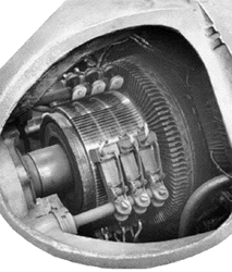
1.Black spots on the collector rings must be removed by rubbing lightly with fine sandpaper. If not removed, these spots cause pitting that requires regrinding the rings.

2. An imprint of the brush, signs of arcing or uneven wear indicate the need to remove the motor from service and repair or replace the rings.
3.Check the collector ring brushes as described under “Brushes and Commutators”. They do not, however, wear as rapidly as commutator brushes.
Bearing Lubrication
Modern motor designs usually provide a generous supply of lubricant in tight bearing housings. Lubrication on a scheduled basis, in conformance with the manufacturer’s recommendations, provides optimum bearing life.
Thoroughly clean the lubrication equipment and fittings before lubricating. Dirt introduced into the bearings during lubrication probably causes more bearing failures than the lack of lubrication.
Too much grease can overpack bearings and cause them to run hot, shortening their life.
Excessive lubricant can find its way inside the motor where it collects dirt and causes insulation deterioration.
Many small motors are built with permanently lubricated bearings. They cannot and should not be lubricated.
Oiling Sleeve Bearings
As a general rule, fractional horsepower motors with a wick lubrication system should be oiled every 2000 hours of operation or at least annually. Dirty, wet or corrosive locations or heavy loading may require oiling at three-month intervals or more often. Roughly 30 drops of oil for a 3-inch diameter frame to 100 drops for a 9-inch diameter frame is sufficient. Use a 150 SUS viscosity turbine oil or SAE 10 automotive oil.
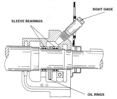
Some larger motors are equipped with oil reservoirs and usually a sight gage to check proper level.
As long as the oil is clean and light in color, the only requirement is to fill the cavity to the proper level with the oil recommended by the manufacturer. Do not overfill the cavity. If the oil is discolored, dirty or contains water, remove the drain plug. Flush the bearing with fresh oil until it comes out clean. Coat the plug threads with a sealing compound, replace the plug and fill the cavity to the proper level.
When motors are disassembled, wash the housing with a solvent. Discard used felt packing. Replace badly worn bearings. Coat the shaft and bearing surfaces with oil and reassemble.
Greasing Ball and Roller Bearings
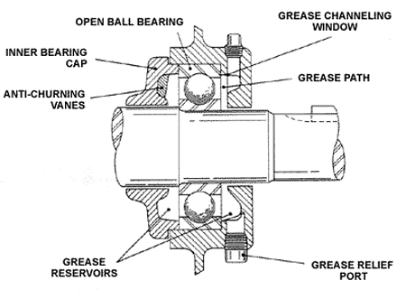
Practically all Reliance ball bearing motors in current production are equipped with the exclusive PLS/Positive Lubrication System. PLS is a patented open-bearing system that provides long, reliable bearing and motor life regardless of mounting position. Its special internal passages uniformly distribute new grease pumped into the housing during regreasing through the open bearings and forces old grease out through the drain hole. The close running tolerance between shaft and inner bearing cap minimizes entry of contaminants into the housing and grease migration into the motor. The unique V-groove outer slinger seals the opening between the shaft and end bracket while the motor is running or is at rest yet allows relief of grease along the shaft if the drain hole is plugged.
The frequency of routine greasing increases with motor size and severity of the application as indicated in Table 1. Actual schedules must be selected by the user for the specific conditions.
During scheduled greasing, remove both the inlet and drain plugs. Pump grease into the housing using a standard grease gun and light pressure until clean grease comes out of the drain hole.
If the bearings are hot or noisy even after correction of bearing overloads (see “Troubleshooting”) remove the motor from service. Wash the housing and bearings with a good solvent. Replace bearings that show signs of damage or wear. Repack the bearings, assemble the motor and fill the grease cavity.
Whenever motors are disassembled for service, check the bearing housing. Wipe out any old grease. If there are any signs of grease contamination or breakdown, clean and repack the bearing system as described in the preceding paragraph.
Heat, Noise, and Vibration
Heat
Excessive heat is both a cause of motor failure and a sign of other motor problems.
The primary damage caused by excess heat is to increase the aging rate of the insulation. Heat beyond the insulation’s rating shortens winding life. After overheating, a motor may run satisfactorily but its useful life will be shorter. For maximum motor life, the cause of overheating should be identified and eliminated.
As indicated in the Troubleshooting Sections, overheating results from a variety of different motor problems. They can be grouped as follows:
- WRONG MOTOR: It may be too small or have the wrong starting torque characteristics for the load. This may be the result of poor initial selection or changes in the load requirements.
- POOR COOLING: Accumulated dirt or poor motor location may prevent the free flow of cooling air around the motor. In other cases, the motor may draw heated air from another source. Internal dirt or damage can prevent proper air flow through all sections of the motor. Dirt on the frame may prevent transfer of internal heat to the cooler ambient air.
- OVERLOADED DRIVEN MACHINE: Excess loads or jams in the driven machine force the motor to supply higher torque, draw more current and overheat.
| Motor Horsepower | Light Duty(1) | Standard Duty(2) | Heavy Duty(3) | Severe Duty(4) |
| Up to 7-1/2 10 to 40 50 to 150 Over 150 | 10 years 7 years 4 years 1 year | 7 years 4 years 1-1/2 years 6 months | 4 years 1-1/2 years 9 months 3 months | 9 months 4 months 3 months 2 months |
- Light Duty: Motors operate infrequently (1 hour/day or less) as in portable floor sanders, valves, door openers.
- Standard Duty: Motors operate in normal applications (1 or 2 work shifts). Examples include air conditioning units, conveyors, refrigeration apparatus, laundry machinery, woodworking and textile machines, water pumps, machine tools, garage compressors.
- Heavy Duty: Motors subjected to above normal operation and vibration (running 24 hours/day, 365 days/year). Such operations as in steel mill service, coal and mining machinery, motor-generator sets, fans, pumps.
- Severe Duty: Extremely harsh, dirty motor applications. Severe vibration and high ambient conditions often exist.
- EXCESSIVE FRICTION: Misalignment, poor bearings and other problems in the driven machine, power transmission system or motor increase the torque required to drive the loads, raising motor operating temperature.
- ELECTRICAL OVERLOADS: An electrical failure of a winding or connection in the motor can cause other Windings or the entire motor to overheat.
Noise and Vibration
Noise indicates motor problems but ordinarily does not cause damage. Noise, however, is usually accompanied by vibration.
Vibration can cause damage in several ways. It tends to shake windings loose and mechanically damages insulation by cracking, flaking or abrading the material. Embrittlement of lead wires from excessive movement and brush sparking at commutators or current collector rings also results from vibration. Finally, vibration can speed bearing failure by causing balls to “brinnell,” sleeve bearings to be pounded out of shape or the housings to loosen in the shells.
Whenever noise or vibration are found in an operating motor, the source should be quickly isolated and corrected. What seems to be an obvious source of the noise or vibration may be a symptom of a hidden problem. Therefore, a thorough investigation is often required.
Noise and vibrations can be caused by a misaligned motor shaft or can be transmitted to the motor from the driven machine or power transmission system. They can also be the result of either electrical or mechanical unbalance in the motor.
After checking the motor shaft alignment, disconnect the motor from the driven load. If the motor then operates smoothly, look for the source of noise or vibration in the driven equipment.
If the disconnected motor still vibrates, remove power from the motor. If the vibration stops, look for an electrical unbalance. If it continues as the motor coasts without power, look for a mechanical unbalance.
Electrical unbalance occurs when the magnetic attraction between stator and rotor is uneven around the periphery of the motor. This causes the shaft to deflect as it rotates creating a mechanical unbalance. Electrical unbalance usually indicates an electrical failure such as an open stator or rotor winding, an open bar or ring in squirrel cage motors or shorted field coils in synchronous motors. An uneven air gap, usually from badly worn sleeve bearings, also produces electrical unbalance.
The chief causes of mechanical unbalance include a distorted mounting, bent shaft, poorly balanced rotor, loose parts on the rotor or bad bearings. Noise can also come from the fan hitting the frame, shroud, or foreign objects inside the shroud. If the bearings are bad, as indicated by excessive bearing noise, determine why the bearings failed. (See Troubleshooting Problems D and L.)
Brush chatter is a motor noise that can be caused by vibration or other problems unrelated to vibration. See Troubleshooting Problem M for details.
Windings
Care of Windings and Insulation
Except for expensive, high horsepower motors, routine inspections generally do not involve opening the motor to inspect the windings. Therefore, long motor life requires selection of the proper enclosure to protect the windings from excessive dirt, abrasives, moisture, oil and chemicals.
When the need is indicated by severe operating conditions or a history of winding failures, routine testing can identify deteriorating insulation. Such motors can be removed from service and repaired before unexpected failures stop production. See “Testing Windings”.
Whenever a motor is opened for repair, service the windings as follows:
- Accumulated dirt prevents proper cooling and may absorb moisture and other contaminants that damage the insulation. Vacuum the dirt from the windings and internal air passages. Do not use high pressure air because this can damage windings by driving the dirt into the insulation.
- Abrasive dust drawn through the motor can abrade coil noses, removing insulation. If such abrasion is found, the winding should be revarnished or replaced.
- Moisture reduces the dielectric strength of insulation which results in shorts. If the inside of the motor is damp, dry the motor per information in “Cleaning and Drying Windings”.
- Wipe any oil and grease from inside the motor. Use care with solvents that can attack the insulation.
- If the insulation appears brittle, overheated or cracked, the motor should be revarnished or, with severe conditions, rewound.
- Loose coils and leads can move with changing magnetic fields or vibration, causing the insulation to wear, crack or fray. Revarnishing and retying leads may correct minor problems. If the loose coil situation is severe, the motor must be rewound.
- Check the lead-to-coil connections for signs of overheating or corrosion. These connections are often exposed on large motors but taped on small motors. Repair as needed.
- Check wound rotor windings as described for stator windings. Because rotor windings must withstand centrifugal forces, tightness is even more important. In addition, check for loose pole pieces or other loose parts that create unbalance problems.
- The cast rotor rods and end rings of squirrel cage motors rarely need attention. However, open or broken rods create electrical unbalance that increases with the number of rods broken. An open end ring causes severe vibration and noise.
Testing Windings
Routine field testing of windings can identify deteriorating insulation permitting scheduled repair or replacement of the motor before its failure disrupts operations. Such testing is good practice especially for applications with severe operating conditions or a history of winding failures and for expensive, high horsepower motors and locations where failures can cause health and safety problems or high economic loss.
The easiest field test that prevents the most failures is the ground-insulation, or “megger,” test. It applies DC voltage, usually 500 or 1000 volts, to the motor and measures the resistance of the insulation.
NEMA standards require a minimum resistance to ground at 40 degrees C ambient of 1 megohm per kv of rating plus 1 megohm. Medium size motors in good condition will generally have megohmmeter readings in excess of 50 megohms. Low readings may indicate a seriously reduced insulation condition caused by contamination from moisture, oil or conductive dirt or deterioration from age or excessive heat.
One megger reading for a motor means little. A curve recording resistance, with the motor cold and hot, and date indicates the rate of deterioration. This curve provides the information needed to decide if the motor can be safely left in service until the next scheduled inspection time.
The megger test indicates ground insulation condition. It does not, however, measure turn-to-turn insulation condition and may not pick up localized weaknesses. Moreover, operating voltage peaks may stress the insulation more severely than megger voltage. For example, the DC output of a 500-volt megger is below the normal 625-volt peak each half cycle of an AC motor operating on a 440-volt system. Experience and conditions may indicate the need for additional routine testing.
A test used to prove existence of a safety margin above operating voltage is the AC high potential ground test. It applies a high AC voltage (typically, 65% of a voltage times twice the operating voltage plus 1000 volts) between windings and frame.
Although this test does detect poor insulation condition, the high voltage can arc to ground, burning insulation and frame, and can also actually cause failure during the test. It should never be applied to a motor with a low megger reading.
DC rather than AC high potential tests are becoming popular because the test equipment is smaller and the low test current is less dangerous to people and does not create damage of its own.
Cleaning and Drying Windings
Motors which have been flooded or which have low megger readings because of contamination by moisture, oil or conductive dust should be thoroughly cleaned and dried. The methods depend upon available equipment.
A hot water hose and detergents are commonly used to remove dirt, oil, dust or salt concentrations from rotors, stators and connection boxes. After cleaning, the windings must be dried, commonly in a forced-draft oven. Time to obtain acceptable megger readings varies from a couple hours to a few days.
Brush and Commutator Care
Some maintenance people with many relatively trouble-free AC squirrel cage motors forget that brushes and commutators require more frequent routine inspection and service. The result can be unnecessary failures between scheduled maintenance.
As indicated in Troubleshooting Problem M on Page 27, many factors are involved in brush and commutator problems. All generally involve brush sparking usually accompanied by chatter and often excessive wear or chipping. Sparking may result from poor commutator conditions or it may cause them.
The degree of sparking should be determined by careful visual inspection. The illustrations shown in
Figure 5 are a useful guide. It is very important that you gauge the degree number as accurately as possible. The solution to the problem may well depend upon the accuracy of your answer since many motor, load, environmental and application conditions can cause sparking.
It is also imperative that a remedy be determined as quickly as possible. Sparking generally feeds upon itself and becomes worse with time until serious damage results.
Some of the causes are obvious and some are not. Some are constant and others intermittent. Therefore, eliminating brush sparking, especially when it is a chronic or recurring problem, requires a thorough review of the motor and operating conditions. Always recheck for sparking after correcting one problem to see that it solved the total problem. Also remember that, after grinding the commutator and properly reseating the brushes, sparking will occur until the polished, brown surface reforms on the commutator.
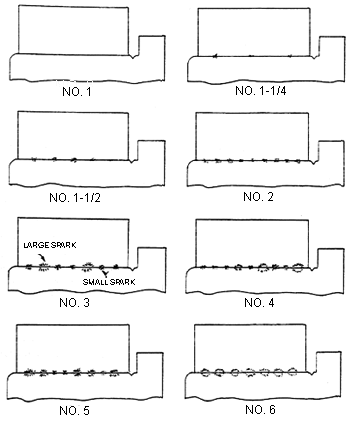
NOTE: Small sparks are yellow in color, and the large sparks are white in color. The white sparks, or blue-white sparks, are most detrimental to commutation (both brush and commutator).
First consider external conditions that affect commutation. Frequent motor overloads, vibration and high humidity cause sparking. Extremely low humidity allows brushes to wear through the needed polished brown commutator surface film. Oil, paint, acid and other chemical vapors in the atmosphere contaminate brushes and the commutator surface.
Look for obvious brush and brush holder deficiencies:
- Be sure brushes are properly seated, move freely in the holders and are not too short.
- The brush spring pressure must be equal on all brushes.
- Be sure spring pressure is not too light or too high. Large motors with adjustable springs should be set at about 3 to 4 pounds per square inch of brush surface in contact with the commutators.
- Remove dust that can cause a short between brush holders and frame.
- Check lead connections to the brush holders. Loose connections cause overheating.
Look for obvious commutator problems:
- Any condition other than a polished, brown surface under the brushes indicates a problem. Severe sparking causes a rough blackened surface. An oil film, paint spray, chemical contamination and other abnormal conditions can cause a blackened or discolored surface and sparking. Streaking or grooving under only some brushes or flat and burned spots can result from a load mismatch and cause motor electrical problems. Grooved commutators should be removed from service. A brassy appearance shows excessive wear on the surface resulting from low humidity or wrong brush grade.
- High mica or high or low commutator bars make the brushes jump, causing sparking.
- Carbon dust, copper foil or other conductive dust in the slots between commutator bars causes shorting and sometimes sparking between bars.
If correcting any obvious deficiencies does not eliminate sparking or noise, look to the less obvious possibilities:
- If brushes were changed before the problem became apparent, check the grade of brushes. Weak brushes may chip. Soft, low abrasive brushes may allow a thick film to form. High friction or high abrasion brushes wear away the brown film, producing a brassy surface. If the problem appears only under one or more of the brushes, two different grades of brushes may have been installed. Generally, use only the brushes recommended by the motor manufacturer or a qualified brush expert.
- The brush holder may have been reset improperly. If the boxes are more than 1/8″ from the commutator, the brushes can jump or chip. Setting the brush holder off neutral causes sparking. Normally the brushes must be equally spaced around the commutator and must be parallel to the bars so all make contact with each bar at the same time.
- An eccentric commutator causes sparking and may cause vibration. Normally, concentricity should be within .001″ on high speed, .002″ on medium speed and .004″ on slow speed motors.
- Various electrical failures in the motor windings or connections manifest themselves in sparking and poor commutation. Look for shorts or opens in the armature circuit and for grounds, shorts or opens in the field winding circuits. A weak interpole circuit or large air gap also generate brush sparking.
From Reliance Electric which has since been acquired by ABB.
Need to develop an effective electric motor testing program?
Related Articles

Keys for Effective Troubleshooting

Corrective Maintenance Task Generation

Availability in a Supply Constrained Environment is the #1 Issue for Refinery Executives

Weibull Point Process Applied to Repairable Subsystems

Energy Savings Through Pump Refurbishment and Coatings

Causes of Overheating in Cartridge Mechanical Seals
