Nuclear Weapons Release Systems & Your Electrical Reliability Program
Dr Anthony Kenneson-Adams. MA. Bsc(Hons). FInstLM. Royal Air Force (Ret’d)
07/11/2023
Introduction
So that title caught your attention!
Those of you who have been following my articles will know that I spent 30 years in the Royal Air Force. For 15 of those years I worked on or had responsibility for aircraft conventional and nuclear weapons release systems. This article will show you how applying the same electrical reliability standards in your plant that we employed on aircraft will enable you to increase your electrical reliability for very little cost. I will also describe how application of these military reliability standards in a paper mill was able to reduce electrical lost time by 60% in just 18 months saving $812,006 in production lost time.
Needless to say, only one standard of reliability is acceptable on a nuclear weapons release system and that is perfection. Though RAF electrical technicians have the very best training available and military aircraft are engineered to the highest standards, the technical skills to replicate the same level of electrical reliability in a paper mill, consumer packaging plant, food production plant, automotive production line, or medical device manufacturer are the same, and are available to all at low cost with a high return on your Investment (ROI). These techniques once applied need professional discipline and a large attention to detail, and this article will cover how you can replicate these techniques, standards, and attention to detail in your business.
Maintain A Life Cycle of Electrical Reliability
My first interaction with high level electrical system reliability was as a RAF engineer responsible for maintaining weapons release systems components such as weapons selection switches, Master Arm Systems Breakers, control column release switches, weapons pylons, and associated cable looms etc. As I had a particular skill set on these systems, I was then asked to produce a training course to teach others the necessary skills for precision electrical reliability. At that time that included crimping, soldering and wire wrapping techniques. However, in this article I will focus on crimping and wiring husbandry and then talk about systems electrical reliability that I have introduced in subsequent posts as a civilian engineering manager and consultant building on my military experience.
For a format to build understanding I will track through the major stages of building electrical reliability.
Design for Reliability
Engineering departments have a major input to building reliable systems and ensuring delivered product meets the design specification. From the outset it is essential to build a robust Requirements Document, be an intelligent customer and question everything during delivery, installation, and commissioning.
However, for me, the most essential part of the reliability design process is to get maintenance involved from Day 1 of the reliability planning cycle. The technicians who will be responsible for the ongoing reliability can inform the engineering design, and thus build in electrical integrity by aligning the design with maintenance standards, ensuring accessibility and building in the ability to sustain electrical reliability during operations.
Commissioning
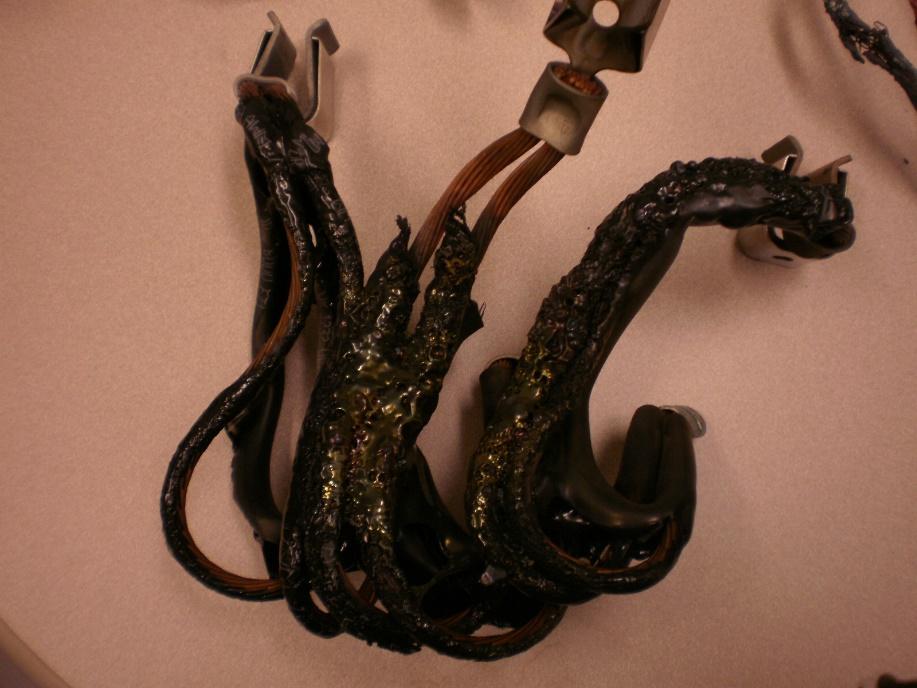
In the photograph below is the result of a catastrophic cable failure. The OEM wiring diagram for this MCC connecting cable stated that the cable should be ‘000’ gauge, however the OEM manufactured the cable assemblies incorrectly with ‘00’ gauge cable and this was not picked up on commissioning or discovered in previous RCPS. As a result, the paper mill had a 5-year history of cable melt downs causing major safety concerns, hard shutdowns, and lost time. The OEM stated the problem was that the user was running the motors too hard, and the business believed the OEM, until I was called in to facilitate a Six Sigma DMAIC root cause problem solving exercise.
Commissioning means check every detail and leave nothing to chance. Failing that, you had better ensure you sign a ‘power by the hour’ contract to focus the attention of the OEM.
Store for Reliability
Who would believe that a company would buy a $50,000 electric motor and then store it outside in a wooden box. Well, I have seen it many times and with components valued well in excess of $50,000. Yes, the weather in Florida may be stable for part of the year but the cycles of hot and cold over even a 24-hour period and the resultant humidity changes will turn a $50,000 motor into scrap or reduce its usable life far more quickly than many would believe.
Likewise, buying motors in bulk to make a saving and then storing them on metal shelves without vibration attenuation, only to have bearing failure on start up should be no surprise. Not only should the shelving not amplify building vibration, but a process should be put in place for every motor shaft to be turned by 1 and ¾ turns every month to ensure weight does not sit on the same place on the bearing for large periods of time. Check the IDCON CBM manuals for motor Preventative Maintenance Condition Monitoring Standards 1 (simplebooklet.com).
Maintain for Reliability
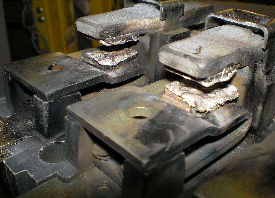
The biggest interaction most maintenance departments will have with their machinery will be during repairs or preventative maintenance. In the photograph below is the cause of a lost time event that resulted in the unplanned shutdown of a paper machine. In this event not only the contactor had to be changed but the fault caused an automatic shutdown losing the felts on which the paper is formed at a cost of $20,000. In addition, the feed lines of paper were completely blocked solid due to the unplanned shutdown, with paper pulp that set like concrete which took an extra 8 hours of lost time to clear.
This was all because this contactor was not the subject of a PM so had not been inspected or cleaned in more than 8 years. Every electrical item must be part of routine inspection, or a timed change out, unless it is on a non-critical system that can be allowed to run to failure, (though not on a nuclear weapons delivery system).
Simple Steps to Maintain Electrical Cable and Connection Reliability
Cable Choice and Handling
On aircraft as in manufacturing plants, cable must be matched to its environment as well as the current carrying capacity. Cables that may get covered in hydraulic oil need a different insulation to that which is used in a hot area or that used in a control room. Take the time during installation and repair to find out which cable is needed and follow the manufacturers instructions for bend radius, temperature, looming etc. This includes during a repair where the technician should question the type of cable already fitted, rather than just replacing it with the same product. In industry I have seen on multiple occasions where an incorrect cable type has been fitted and periodically replaced when it has failed, rather than questioning why it failed and ascertaining if the cable is correctly matched to the application. Question everything!
Crimping Quality
One of the most common areas for open circuits and short circuits in electrical systems in industry that is not tolerated on aircraft is poor quality crimping for cable termination. Crimping is advertised as a low skill of hand and high reliability joint when compared to soldering which it is, but to get that repeatability every crimp must follow a series of highly disciplined steps executed by trained and focused personnel. These simple steps will ensure that you maintain electrical integrity of crimped joints for the life of your installation.
- Cleanliness. Ensure the cable and crimp are free from dirt, dust, grease, oil etc. Anything that is crimped into a joint other than the metal of the conductors will be a point of resistance that will cause heat and joint failure.
- Cable stripping. Never use a knife to remove the insulation of a cable. You will either remove conductors altogether or nick them, which will ensure they fail at some point in the future. It is surprising how few conductors have to be removed on say a 20-gauge cable to turn it into a 22-gauge cable. Use a semi-automatic wire stripper or other device that is regularly checked to ensure every cable stripped removes every bit of insulation every time without any damage to the conductors. Only strip the amount of cable that is identified in the crimping method sheets. If you cannot find the manual, strip enough insulation so that when the crimp is completed that the conductor is standing proud of the crimp ferrule at the connection end by no more than about 1mm to 2mm based on the cable gauge and that the insulation on the cable end is snug up against the ferule.
- Crimp Selection. Select the cable crimp based on the gauge of the cable. It is never acceptable to use any other crimp or to fold a conductor in half to make use of a larger crimp. Crimps only provide electrical and mechanical integrity when there is uniform deformation of all the conductors. Gaps between conductors cause arcing resulting in failure. Too many conductors crimped into a tag or ferule and the cable is effectively being cut when crimped and will eventually fail.
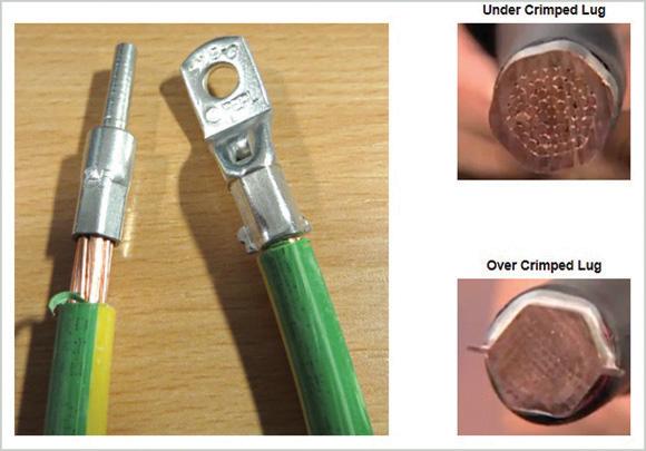
- Match the crimp, cable size and crimping tool. Ensure the crimp and the crimping tool are manufactured by the same company. This is the only way to ensure you will get uniform deformation. Uniform deformation means that each conductor is deformed to make maximum contact with the other conductors with no voids between the conductors, as in the diagram below. Furthermore, ensure there is no debris in the crimp and all conductors are undamaged and all are inside the ferrule of the crimp body. Stray conductors on the outside of the crimp body will cause short circuits. It is also good practice never to crimp onto a single strand cable without using a crimp and tools specifically for the job.

- Ratchet Crimp Tools. The most reliable crimps are always made with tools that have a ratchet mechanism. This ensures that the correct pressure is applied every time to ensure uniform deformation of each conductor. Maximising the reliability of a crimped tag includes the use of the go/no go gauge prior to each use to check crimp tool jaw wear if a gauge has been supplied with the tool and don’t scrimp on the cost of a crimping tools. Buying the cheaper crimping tool is false economy where say purchasing a $300 crimping tool is protecting a $50,000 motor or your entire production process. This way of thinking comes from an incident in the 1970’s where we lost an aircraft and its crew when a single crimp failed on a rudder actuator. Don’t risk safety or production on a poor reliability cheap crimping tool.
- Inspect the crimped joint. After crimping, visually inspect the joint to ensure it is properly formed. The crimped area should be smooth and evenly compressed around the wire, with no visible gaps or deformities. Use a magnifying glass if necessary to examine the joint closely.
- Perform a pull test. If possible, perform a pull test to check the strength of the crimped joint. Apply a moderate amount of force to the wire to ensure it is securely held by the connector. If the wire easily pulls out the crimp, conduct a simple Root Cause Problem Solving exercise, perhaps a simple 5Y before moving on. Was it the worn tool, wrong tool, missing conductors, wrong crimp etc. Learn before you move on.
- Conduct electrical testing (if applicable). If the application requires it, perform electrical testing to verify the integrity of the crimped joint. This may involve measuring resistance, checking for continuity, millivolt drop test or conducting other appropriate tests.
- Practice and Experience. Remember, practice and experience play a crucial role in achieving consistent results. It is important to familiarize yourself with the specific crimping tools, connectors, and wires you are using, and to follow the manufacturer’s instructions and guidelines for optimal results.
- Torque load every crimp. Another simple choice a business can make to ensure that every connection, be that mechanical or electrical has optimized reliability is to enforce that every crimp is torque loaded when connected. This is better understood but still poorly practiced for mechanical fasteners but here I will focus on electrical connections.
Every crimped tag connected by a bolt or screw can be torque loaded, even down to terminal block screws of a few millimetres. Three white knuckles is not a standard, and such practice is likely to take a screw or bolt through the yield point. This will destroy any potential for optimum compressive force and thus the fastener will come loose. Likewise, not enough torque will also result in the screw working loose. Maximum compressive force can be as low as 5% of the range of possible torque that can be applied to a fastener, so is it any wonder connections work loose causing an ‘open circuit,’ and in high current applications cause arcing, hot spots, and fires. If you go to the trouble to select the right cable, insulation, crimp, crimping tool, and wire stripper, why would you not finish the job properly and use a torque tool to ensure the highest reliability standard.
- Thermal Imaging. This is a technique that is invaluable for checking the integrity of electrical installations without even having to shut down the machine. Some Machine Control Centres (MCCs) and some switching gear already come fitted with an IR window which can also be a retrofit. In these cases, use of a thermal camera can instantly highlight if you have a problem with a hot spot in an installation caused by any number of defects. I have also applied thermography to rounds carried out by maintenance and by operators to check almost daily not only for electrical hot spots but also to check the health of bearings or to find out where a pulp feed line is narrowing. This saves considerable fault diagnosis time. This is a relatively inexpensive tool when compared to the loss of equipment and production down time when a failure occurs.
- Motor Testing. There are many articles on the physics and opportunities for reliability and life extension of high value motors. If you have high-value motors in your production process, you should at a minimum investigate the benefits that motor condition testing can bring for reliability and longevity of your motors. When testing the electrical integrity of high-value electrical production motors, several options are available to ensure their proper functioning and here are some common methods:
- Insulation Resistance Test: This test measures the resistance between the windings and the motor’s frame to assess the condition of the insulation. It helps identify potential insulation breakdown or moisture ingress. Insulation resistance testers apply a high voltage to the motor and measure the resulting current flow. It applies a high voltage (typically 500 to 1000 volts) to the motor windings and measures the resulting leakage current. The test helps assess the condition of the motor’s insulation system and identifies potential faults. Be advised this method is stressing the insulation of your motor windings so use under advisement of the OEM.
- Surge Comparison Test: Also known as surge testing or surge impedance testing, this method checks the motor windings for insulation faults, such as turn-to-turn shorts or coil-to-ground shorts. A high-voltage surge is applied to the windings, and the resulting waveforms are compared to reference waveforms to detect any anomalies.
- Polarization Index (PI) Test: The PI test is used to evaluate the insulation resistance of the motor over an extended period. It involves measuring the insulation resistance at specific time intervals (typically 1, 10, and 60 minutes) after applying a test voltage. The ratio of the insulation resistance at 10 minutes to the insulation resistance at 1 minute provides the PI value. A decreasing PI value may indicate insulation degradation.
- Partial Discharge (PD) Test: PD testing is performed to detect partial discharges within the motor windings or insulation. Partial discharges can lead to insulation deterioration and ultimately motor failure. PD testers measure the magnitude and frequency of the discharges to determine the motor’s condition.
- Winding Resistance Test: This test measures the resistance of each individual motor winding using a low-resistance ohmmeter. By comparing the measured values with the motor’s specifications, any significant deviations can indicate potential issues like shorted or open windings.
- Vibration Analysis: Vibration analysis is used to monitor and diagnose the mechanical condition of the motor. It helps identify abnormalities such as unbalanced rotors, misalignment, bearing wear, or loose connections that may affect the motor’s electrical performance. This can now be carried out remotely with blue tooth enabled accelerometers and automatic monitoring sending motor condition messages to your phone.
- Current Analysis: Monitoring the current signature of the motor during operation can provide insights into its electrical health. Current analysis helps detect abnormalities like high current, unbalanced phases, or excessive harmonics, indicating issues such as winding faults, rotor problems, or supply irregularities.
Rather than doing all these tests in house, requiring cost of test equipment and trained personnel, I recommend that you call in your motor supplier who for a fee will carry out the testing on your behalf. This method is cost effective and produces a health report for every critical motor.
Preventative Maintenance
In the example I stated where one plant saved $812,006, once we had established a recovery plan for poor crimping that had caused open and short circuits the single biggest impact in reduced lost time was instituting world-class PMs. The company already had a PM for arc flash testing, and they put IR windows on all their high current MCC buckets. So, I added a PM to open all the buckets on an 18-month rotation after thermal imaging, to clean the buckets, inspect contacts, and check the cable fasteners were tight. This was a very quick examination as after applying the correct torque to each bolt they then had a witness mark applied so correct torque was now simply a visual check.

Operate for Reliability
Now don’t mess it up. Once you have built reliability into your process operate your machinery to the OEM specification or at least understand the consequences of running that motor or other component at 5% over its maximum for its life cycle or outside the operating temperature etc.
Maintain the discipline of reliable crimps and build electrical PMs that will maintain your reliability. Clean up spills, set up PMs to maintain reliability and regularly check and clean cabinets and looms. Now you will be some way toward the levels of electrical reliability demanded for military aircraft weapons release systems and with minimum cost. Applying just some of these ideas will make a difference to the electrical reliability of your machinery and your plant.
If you have any questions, contact me at Anthony.kennesonadams@project7consultancy.com

Related Articles

Achieving TPM Excellence the Fast Jet Way

Maintenance, Lean Processes and the Drive to Net Zero

The Maintenance Leader’s Journey from ‘Command and Control’ to ‘Mission Command’

Industrial Coaching

The 8 Pillars of TPM