Increasing Pump Reliability and Life
Michael Mancini, Mancini Consulting Services Pumps & Systems
In Mel Brook’s movie, History of the World, Part 1, Moses comes down from Mount Sinai carrying three tablets. “People of Israel”, Moses exclaims, “I bring you these 15 [dropping one tablet]. . . 10 Commandments!” Only a handful of people know the untold commandments. In this article, we will review two of these and the reasoning behind them, they just might help when increasing pump reliability and life.
- Commandment 11: Thou shalt always operate centrifugal pumps at their best efficiency point.
- Commandment 12: Thou shalt avoid prematurely opening pump wear ring clearances.
Commandment 11: Operation at BEP
The majority of the failure mechanisms that significantly reduce the reliability and life of a centrifugal pump are caused by operation away from the pump best efficiency point (BEP). To achieve best-in-class life, it is essential to either operate close to the pump BEP (which is always the preferred method) or to provide provisions that anticipate the various effects of off-BEP operation and attempt to mitigate these consequences.
The pump BEP is the operating condition at which the angle of the fluid entering the impeller is parallel to the impeller blade. The farther that one operates away from the BEP, the greater dissimilarity between the flow incidence angles and the inlet vane geometry. Similarly, as the pump operation becomes farther removed from BEP, the possibility of serious problems and the severity of existing problems will almost always increase.
The most detrimental effects of operation that affect pump reliability and life, away from the best efficiency point, are experienced due to:
- Suction recirculation
- Discharge recirculation
- Larger radial loads
- Opening of wear ring clearances
Each of these problems will induce other problems that negatively impact reliability and performance, such as separation-cavitation, axial shuttling or increased shaft deflection. These problems will decrease your pump’s reliability and life.
Suction Recirculation
Suction recirculation most often occurs when off-BEP operation is coupled with large impeller eye areas. The stalled area on the pressure side of the inlet vane, caused by the mismatch between the fluid angle and the blade angle, results in the formation of fluid swirl. The result is a separation of the fluid from the vane that has enough room (via the large inlet area) to recirculate.

When severe, the fluid circulates out of the impeller eye, interfering with normal suction flow. This fluid swirl can cause localized pressure drops, which reduce the total head generated and cause the suction pressure to fall below the fluid vapor pressure. The effect of this pressure drop is known as separation/cavitation.
The consequences of suction recirculation are increased rotor vibration from fluid instability and impeller damage due to cavitation. The design emphases to significantly reduce or eliminate these issues are:
- Reduce the impeller eye diameter to the extent allowed by suction (NPSHA) conditions
- Operate the pump as close to its BEP as possible to minimize separation effects
- Provide state-of-the-art air foil shapes to the impeller inlet vanes to be more permissive of off-peak operation
1. Reducing the Impeller Eye Diameter
Limiting the suction specific speed (NSS) of the impeller can reduce the impeller eye diameter. Suction specific speed (NSS) is a dimensionless parameter that helps define impeller geometry. When designing an impeller, lower values for suction specific speed lead to smaller eye inlet areas and less susceptibility to inlet fluid recirculation.
Where:
Q = Flow per eye at the pump’s best efficiency point (gpm)
rpm = Pump speed
NPSHR = Net positive suction head required
Empirical data has shown that the failure frequency of pump components significantly increases with an NSS > 11,000 based on a 3 percent ΔH. This analysis is based on J. L. Hallam’s refinery industry study of pumps handling hydrocarbons. For water applications, a maximum NSS of 9,500 should be used to achieve reliable operation.

2. Operation Near the BEP
The affinity laws state that flow is proportional to the change in speed or diameter, and that total developed head is proportional to the square of the change in speed or diameter:
Where:
Q = Flow (gpm)
N = Speed (rpm)
D = Outside diameter
If the pump is operating away from its BEP flow for sustained amounts of time, the affinity laws can be used to modify impeller output to operate more closely to the BEP. This can be accomplished by changing the impeller diameter or by upgrading to a VFD.
Changing the pump speed is a more costly design change; however, it allows the pump to operate at its BEP for its whole range of operating requirements. Changing the impeller diameter only allows the pump to operate at its BEP for a single operating mode.
3. Bias-Wedge Impeller Design
It may not always be possible to run the pump near BEP if it is subjected to variable operating conditions. For these situations, the impeller inlet blade geometry can be redesigned as an air foil to further reduce separation effects at off-peak operation. This modification is typically referred to as a bias-wedge impeller.
With this modification, divergent flow angles follow the more rounded air foil blade shape more closely, reducing separation effects. This method is best applied if the pump is tested to obtain actual performance so that the flow approach angle can be determined.

Discharge Recirculation
Like suction recirculation, the generic root cause for discharge recirculation is a combination of large areas that allow the formation of fluid swirl and operation removed from the pump’s best efficiency flow that causes a mismatch in the fluid and volute cutwater inlet vane angles.
The fluid swirl intermittently disrupts the pressure regions on both sides of the impeller, significantly reduces the damping characteristics of the wear rings and has an erosive nature. The consequences are:
- Rotor axial shuttling
- Increased vibration resulting from less damping
- Accelerated erosion of the volute cutwater, diffuser inlet blades, and/or impeller exit vanes
The design emphases to eliminate the detrimental effects of discharge recirculation are:
- Operate the pump as close to its BEP as possible to minimize separation effects
- Provide a filter to straighten the fluid swirl through an annulus on each side of the impeller created by a properly sized Gap A and Gap C
- Provide a bias ring design to provide unidirectional thrust andeliminate axial shuttling
Gaps A & C
The fluid swirl can be straightened by forcing the fluid through a tight-fitting orifice of sufficient length. This orifice is formed through a re-design of the casing and impeller.
Gap A, the orifice clearance, is defined as the radial clearance between the impeller exit shroud and the volute inlet shroud:
Where:D3′ = Volute inlet shroudD2′ = Impeller exit shroud
Gap C, the orifice length, is the amount that the impeller exit shroud is overshadowed by the volute inlet shroud:
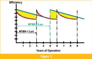
Referring to Figure 5, the figure on the left depicts the existing design, which has insufficient Gap A or Overlap. The figure on the right represents the recommended design.


The proper Gap A is approximately three times the design wear ring clearance. The optimum Gap C, which completes the flow straightening orifice, is four to six times Gap A.
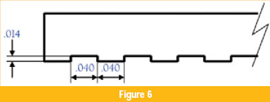
Figure 6 shows the positive effect of the proper Gap A. The idea is to eliminate all thrust reversals for the full range of flow. Note that not only is the thrust uni-directional, but the magnitude is also significantly less.

Bias Ring Design (Double-Suction Impellers)
Both welding and the incorporation of Gaps A and C rings are costly modifications and may not be financially feasible for non-critical or low-energy applications. An alternate solution is to live with the fluid swirl but redesign the pump to obtain uni-directional thrust for any operating mode by creating an axial pre-load on the pump rotor. By arranging the bores at different diameters, a continuous unidirectional axial thrust is created:
Where:
Taxial = Axial thrust (lb)
Pd = Discharge pressure (psi)
Ps = Suction pressure (psi)
The larger wear ring bore diameter should be designed on the inboard end of the pump to place the shaft in continuous tension.

Increased Radial Loads
Hydraulic radial loads are related to the energy output and the operation of the pump relative to its BEP. The radial load is expressed as a function of the impeller diameter, impeller width (including shroud thickness) and discharge pressure. These radial loads act perpendicularly to the axis of the pump shaft in the direction of the volute cutwater, causing the shaft to deflect.
Increased radial loads associated by operation away from BEP can be offset by incorporating either a dual volute or a diffuser into the design of the pump in lieu of a single volute. The placement of the diffuser blades or dual volute cutwaters more efficiently balances the pressure fields at any operating regime, thus reducing the unbalanced radial loads to acceptable limits.
Commandment 12: Premature Opening of Wear Ring Clearances
One of the most significant factors in increasing pump reliability and life is the maintenance of design clearances. The premature opening of wear components clearances is especially damaging to a pump’s reliability and life. The wear components act as water lubricated bearings and provide stiffness and damping to the pump rotor. The wear components also limit internal recirculation and directly impact overall pump efficiency.
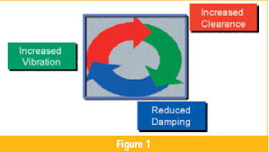
Opening wear component clearances geometrically reduces rotor stiffness and damping, intensifying the relative motion between the rotating and stationary elements caused by normal pump external forces. Additional contact of the wear components caused by this motion increases the clearance, further reducing rotor damping and increasing relative motion. This vicious cycle continues until high vibration, loss of performance or other issues lead to the pump being removed from service.
Causes
Wear ring clearances open at an increased rate when the stationary and rotating wear surfaces come into contact. The most common causes of contact are high vibration amplitudes, increased shaft orbit and non-centerline compatibility of stationary close-clearance bores (wear rings, sleeve bearings, balance sleeves) to the true shaft centerline.
In addition to the causes discussed in Part One, some of the major factors that influence the premature opening of the wear ring clearances are described below.
Impeller and Coupling Imbalance
Balance tolerances are typically expressed as a function of the component weight and the pump operating speed (see Equation 1).
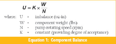
Best-in-class processes achieve a rotor balance < 1W/N for high energy services and < 4W/N for other services. To achieve 1W/N, certain conditions must preexist:
- All keys must be fitted to keyways with no excessive stock or unfilled areas (as would occur when using square instead of full-radius keys)
- The impeller must have an interference fit-up to the shaft
- Shaft concentricity (total indicated runout, T.I.R.) cannot exceed 0.001-in
- Impeller hub turn T.I.R. cannot exceed 0.002-in
- Split rings, when used, must be manufactured to maintain circularity of the bore with exact fit-up of the split ring halves
Angular or Parallel Pump-to-Driver Misalignment-Horizontal Pumps
Angular and parallel pump-to-driver misalignment in horizontal pumps is usually the result of unevenness of the pump mounting pads and baseplate, distortion due to thermal growth or poor maintenance processes. Routine maintenance and inspections are often completed on the pump internal elements while the baseplate, barrel or discharge head remain unchecked. As installations age, it is important to periodically check that the baseplate and pump mounting surfaces have not been distorted through external forces, deteriorating grout or other factors. Misalignment due to thermal growth relates predominantly to foot-mounted pumps in high temperature services. In these instances, centerline mounting of the pump should be considered.
Many techniques are used to achieve proper pump-to-motor alignment. State-of-the-art laser systems can provide information for both cold and process temperature conditions.
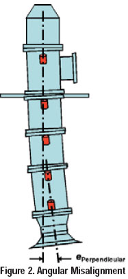
Angular or Parallel Pump-to-Driver Misalignment-Vertical Pumps
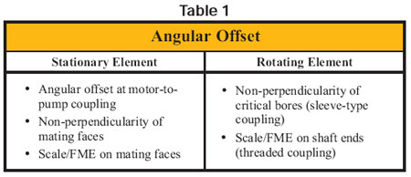
Angular misalignment in vertical pumps occurs as a result of mating faces that are not parallel to each other and perpendicular to the true shaft centerline (see Figure 2). Primary among these conditions are the misalignment of the motor-to-pump shaft, distortion of the discharge head over time and build-up of FME (foreign material exclusion) that can change the relationship between mating faces.
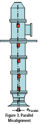
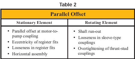
Parallel misalignment in vertical pumps occurs as a result of eccentricities and/or excessive clearance in register fits, non-adjustability of the motor to the discharge head and poor assembly practices (see Figure 3).
Assembling vertical pumps horizontally will also lead to parallel misalignment, even when critical fits are within tolerance, and especially when many column/casing sections are involved. Each component will sit on the bottom of its register fit, resulting in a stack-up of the individual clearances and eccentricities. Better practices include assembling the pump in the vertical orientation where the centerline relationship of each added component can be checked during assembly, or rotating the assembly 180-deg after the installation of each stage piece.
Static Shaft Bow
Shaft straightness is a function of material selection, the process to produce the raw bar and the manufacturing process to achieve the final product. Preferred shaft run-out is maintained at or below 0.001-in and should not exceed 0.002-in. Many specifications allow 0.001-in total indicated runout (T.I.R.) for each foot of shaft length. This is unacceptable, and manufacturers should be encouraged to meet the more stringent criteria.
In addition, neither mechanical nor thermal straightening should be used to restore shaft straightness since internal stresses will relieve themselves under load and the shaft will assume its former shape. Shaft straightening should be prohibited from internal and sub-vendor processes.
Dynamic Shaft Bow
Dynamic shaft deflection relates to operation at or near any of the rotor critical speeds. Most pumps are designed such that the operating speed is a minimum 25 percent removed from the critical speed. As bearing clearances increase, the stiffness and rotor critical speeds decrease. If sufficient margin is not provided in the original design, the critical speed can fall into the operating speed. It is recommended that specifications for new equipment, or when possible for upgrading existing units, require a minimum 35 percent margin between the operating and first critical speeds. This can be accomplished by:
- Increasing the shaft diameter
- Reducing the bearing span
- Upgrading to a material with a higher modulus of elasticity
Component Looseness and Improper Component Tolerances
Strict manufacturing tolerances are required to obtain centerline compatibility of all close clearance components and minimize relative motion between rotating and stationary assemblies. Theoretically, the summation of all tolerances must be less than one-half the bearing clearance to avoid contact (see Equation 2).

Existing pump components are usually not designed or manufactured to attain these exacting standards. Centerline compatibility is most easily achieved by requiring interference fit-up of mating components in both rotating and stationary elements. Additionally, concentricity of all critical locating bores and turns as well as perpendicularity of mating faces to the true shaft centerline need to be maintained at strict limits.
Material Galling
Certain materials in the martensitic chrome steel group (such as type 410) have high galling tendencies. This can be compensated for by treating the surfaces to a hardness exceeding 50 Rc, so the materials bounce in lieu of galling when contacted. Achieving this value can be accomplished through hardening, direct laser deposition (DLD) or laser hardening of the material itself. When hardening wear components above 50 Rc, note that there should be no differential hardness between the two components.
Another option for martensitic chrome steels is to increase the sulfur content to types 416 and 420F, which increases the material lubricity. Type 416 is sensitive to stress corrosion cracking when subjected to tensile loads and certain boundary conditions, so it should be avoided as an impeller wear ring material. Synthetic materials are also gaining popularity due to their non-galling tendencies and capability of operating at reduced clearances.
Detecting Wear Clearance Opening
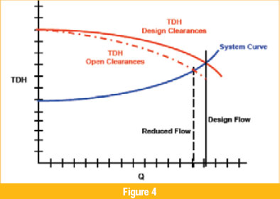
Increased wear ring clearances increase internal recirculation, reducing both the total flow delivered to the system and the pump efficiency. Increased clearances will result in the following observable changes:
- Loss of flow and head in an unthrottled system
- Increased motor amps in a throttled system
- Increased vibration amplitudes at the 1X frequency
Thermodynamic testing methods can also be used to detect and trend wear component clearance opening. This testing, exemplified by the British Yatesmeter system, measures the efficiency of existing unit performance with extremely accurate pressure and temperature measurements. By trending internal clearance (inversely proportional to efficiency), pump operating life can be predicted by monitoring internal clearances and evaluating to a pre-established limit. The Yatesmeter can be used as a performance-based monitoring tool to maximize operating life and help avoid mid-cycle failures.
Mitigating Processes
Lomakin Grooving
To increase rotor damping and make the pump more permissive to increasing rotor vibration with time, Lomakin grooving of the wear components is highly recommended. Lomakin grooves are a square grooving pattern of shallow depth. Note that these grooves should be completed on only one of the mating surfaces of close-clearance component pairs.
Lomakin grooving has proven to significantly increase the rotor stiffness over smooth-on-smooth services.
Inspection and Manufacturing Procedures
Except for material considerations, mitigating the premature opening of clearances involves good operating practices and stringent inspection and manufacturing standards to ensure proper pump assembly and construction. To slow the rate of wear clearance opening, it is important that the original condition of the pump provides the optimum environment for the wear component. This means that all critical bores must be concentric to the true shaft centerline, the shaft must not have excessive run-out and all critical mating faces must be both parallel to each other and perpendicular to the true shaft centerline.
To ensure that these conditions exist, it is often necessary to provide detailed specifications, both for inspection processes and for OEM tolerances. Many pumps are designed for multiple markets, so the default tolerances may not be specifically designed for the intended service. Additionally, specifications for procuring new equipment or inspecting existing equipment are often vague, offering no acceptance criteria for work completed. Investing in more detailed specifications, thorough inspections and improved materials can drastically assist in increasing pump reliability and life.
Michael Mancini is president of Mancini Consulting Services, a company dedicated to increasing the overall reliability and life of pumping systems through strategic programs, root cause analysis, specification development and in-depth training. Mancini has spent the past 35 years dedicated to all stages of pump design and maintenance, working side-by-side with many renowned pump designers during his tenure as Vice President of Worldwide Aftermarket for Ingersoll-Dresser Pumps.
Related Articles

OEE: Overall Equipment Effectiveness
What the Pump Was Designed to Do and Why it Doesn't Do it
What is Wrong with the Modern Centrifugal Pump?

Digging Up Savings: Go with the Flow
Chain Drive Design Recommendations

Classifying Chemicals to Assure Effective Sealing